Background: With the recent reports of success, there is now increasing use of cryoablation as a standalone, minimally invasive procedure to treat various cardiac arrhythmias. With increased use, a need for new devices and treatment strategies to deliver improved outcomes has emerged. In this study we investigated the performance of a new super critical nitrogen (SCN) epicardial cryoprobe for the targeted ablation of cardiac tissue. We hypothesized that the SCN technology would enable the rapid, effective delivery of ultra-cold temperatures thereby enabling more effective ablation.
Methods: Assessment included calorimetry, isotherm distribution, repeatability and ablation capacity in a heat loaded ex vivo tissue model.
Results: The SCN device repeatedly generated >2 cm diameter freeze zones in <2 minutes. Calorimetric assessment revealed cooling power >325 W. Isothermal profiling revealed penetration of the -20°C, -30°C and -40°C isotherms to a diameter of 2.2 cm, 2.1 cm and 1.9 cm in a 2.3 cm ice ball following a 3 minute freeze resulting in ∼90% of the frozen volume below -20°C, 80% below -30°C and >65% below -40°C. Tissue studies revealed the generation of a full thickness (5-10 mm) cryogenic lesion within 1 min with an opposite (transmural) surface temperature of <-60°C under a circulating 37°C heat load.
Conclusions: These studies suggest that the SCN epicardial cryoprobe may provide for rapid, effective, controllable freezing of targeted tissue. The ablative power also offers the potential of improved safety via a reduction in procedural time compared to current devices potentially opening new avenues for cryoablation to treat other cardiac arrhythmogenic disorders.
cryoablation, super critical nitrogen, atrial fibrillation, epicardial ablation. cardiac ablation
Abbreviations
AF: Atrial fibrillation; AFFIRM: Atrial fibrillation follow-up investigation of rhythm management; HRS1: 2 mm×100 mm smooth tip SCN cryoprobe; HRS2: 3.4 mm×100 mm corrugated tip SCN cryoprobe; JT: Joule-Tompson; RFA or RF: Radiofrequency ablation; SCN: Super critical nitrogen
Hospitalization of patients with atrial fibrillation (AF) has increased several fold in recent years, currently impacting an estimated 2.5 million adults in the US [1]. This increase is influenced by a more sedentary lifestyle coupled with an aging population that has survived other medical conditions [2]. Current estimates suggest that by 2050, 15 million Americans will suffer from AF [3]. Congestive heart failure remains the leading cause of hospitalization in patients over 65 and results in the largest Medicare expenditure [4]. AF is the most common arrhythmia in patients and is a major cause of congestive heart failure [5]. For instance, AF is present in 10-15% of patients with congestive heart failure and is highly prevalent in functional class IV patients [6,7]. AF also causes stroke and is a predictor of mortality [4]. Patients with AF have a two-fold increase in risk of death and a four-fold risk of thromboembolic stroke [8].
Pharmacological control of AF has been comprehensively reviewed [4,8-10]. The foundation of the AF pharmacologic treatment involves either cardioversion and rhythm control or a rate control approach combined with anticoagulant therapy. Several studies including AFFIRM (Atrial Fibrillation Follow-up Investigation of Rhythm Management) have evaluated these strategies, concluding that lower mortality and increased efficacy is associated with rate control paradigms [8]. A variety of drugs are used to treat AF including amiodarone derivatives, atrium selective channel blockers and gap junction modulators. While other agents are being tested, they all have a degree of toxicity and limited effectiveness which has led to the development of devices designed to generate a set of lesions to prevent arrhythmias [9,11-15]. Studies comparing ablation to pharmacological intervention suggest that ablation may provide a more effective means for maintenance of normal sinus rhythm. Novak [9] reviewed six trials (over 1000 patients) and reported that in patients with primarily paroxysmal AF who failed at least one antiarrhythmia drug, 80% remained AF free following ablation. The use of radiofrequency ablation (RFA) is currently common practice in treating arrhythmia [16], yet a number of complications are associated with RFA, including tissue burning/charring/popping, micro bubble formation, tamponade, pulmonary vein stenosis, and phrenic nerve and esophageal damage. There is also a high degree of recurrence and pain associated with RF therapy. Cryoablation has been shown to be a viable and safer alternative to RFA for the treatment of AF [13]. Data from direct comparisons between the two are limited [11]. Ablation to treat AF, however, seems to be reasonably safe with a lower complications rate [17].
Cryoablation is an effective minimally invasive alternative to cardiac surgery and RFA offering patients a quicker recovery and reduced side effects [18,19]. Numerous studies and reviews have been published detailing various cryosurgical devices and procedures to apply freezing temperatures to a target tissue [20-40]. Continuing improvements to cryoablation device design and their application may further increase its utilization for the treatment of multiple disease states [40-43]. AF can be managed using cryoablation via both epicardial and endocardial based approaches. Cox, et al. [44,45] have used surgical incisions combined with cryoablation of the coronary sinus to ensure interruption of conduction across the posterior-inferior portion of the left atrium. Gaita and associates [46] have successfully treated AF by linear cryoablation of the tissue between the four pulmonary veins and the mitral annulus [47].
With reports on the success of cryoablation for AF treatment, there is now increased interest in using cryoablation as a standalone, minimally invasive procedure to treat all variants of cardiac arrhythmias. Cardiac cryosurgery requires modified freezing dosimetry, which varies with the type of lesion under treatment. The primary targets are the modified myocytes constituting the conduction system. In these applications, the probe is cooled to -70° to -80°C for two to four minutes, which generally is sufficient to ablate the cardiac tissue [48-52]. The tissue temperature at the site of the aberrant myocytes will be in the range of -20 to -30°C. Linear lesions or point lesions, depending on the structure of the probe, are produced. Ventricular lesions require deeper freezing.
Knowledge of the expected performance of a cryosurgical probe is critical to obtain optimal outcomes [53-55]. With good contact with the tissue to insure efficient heat transfer, a probe temperature of about -80°C, cooled by pressurized argon or nitrous oxide, takes ∼5 minutes to freeze tissues to a depth of about 0.5 cm. The duration of each freeze depends on the target site tissue thickness and vascularity. Transmural lesions are not easy to produce, and numerous studies have shown the limitations of today’s cryodevices to achieve the necessary thermal penetration through cardiac tissue, especially when applied in a fully beating non-occluded blood flow scenario [52,56,57].
In practice, today’s cryoablation devices yield similar cooling power at the cryoprobe tip attaining surface temperatures of ∼-80°C under thermal loads [58]. When applied in a epicardial cardiac tissue ablation procedure (Cryomaze or other), this thermal limitation results in lengthy periods necessary to generate a single, sometimes uncertain, transmural lesion (3-5 minutes per site) with differential efficacy based on tissue thickness. These limitations necessitate multiple overlapping and lengthy applications to generate a contiguous lesion, while still retaining uncertainty as to the delivery of an “ablative dose”. This creates a less-than-optimal treatment paradigm, thereby limiting utilization of cryoablation for the treatment of various cardiac arrhythmias [39,59,60]. As such, there is a compelling need for a cryoablative device capable of rapidly creating transmural lesions with full control of the freezing process.
In order to overcome these challenges, we have developed a new cryoablation device, which utilizes Supercritical Nitrogen (SCN), and a series of cryoprobes for the epicardial surgical freezing of cardiac tissue. Studies have shown that SCN offers the ability to overcome the limitations of current Joule-Tompson (JT) based cryoablation devices by delivering greater work capacity via its liquid-like heat extraction properties which are more effective than gas [61-64]. This enhanced heat extraction capacity offers the potential to deliver ultra-cold freeze temperatures deep into tissue under high heat load conditions, such as those experienced when utilizing cryoablation in cardiac ablation settings. In effect, this technology may provide a platform enabling a precise, minimally invasive treatment path for cardiac cryoablation. Given the increased utilization of cryoablation for the treatment of cardiac arrhythmias coupled with the importance of an understanding of cryoprobe performance for optimal application, a series of ex vivo studies were conducted to characterize the performance of the SCN epicardial cardiac cryoprobe. Our results demonstrate that the SCN system provides the rapid delivery of ultra-cold temperatures deep into tissue under high heat loads, supporting its potential application for the treatment of various cardiac arrhythmias.
Super critical nitrogen system and cryoprobes
All tests were performed using the prototype SCN cryoablation device with a start cryogen pressure of 1300 psi±100 psi. Two epicardial cryoprobe designs were evaluated. The epicardial surgical cryoprobe designs included 2 mm×100 mm smooth tip ablation segment (freeze zone) (HRS1) and a 3.4 mm×100 mm corrugated tip ablation segment (HRS2) at the distal end of the probe. The cryoprobes were connected to the SCN cryoconsole via a 3 m umbilical. For analysis, the cryoprobe was positioned in the respective test fixtures containing medium and then activated for a freeze time of 2 or 3 minutes (assay dependent- see details of specific testing below).
Calorimetry assessment
Calorimetry testing was conducted using a 30 mm t-style magnetic stir-bar placed into the bottom of a 20 oz double walled foam insulated vessel. The insulated vessel was filled with 454 mL of water and a ∼20 mm thick polystyrene lid was placed on top. The setup was placed on a magnetic stir plate and the speed was set to the highest setting in which the stir-bar maintained uniform spinning (setting 8 out of 11). The cryoprobe ablation zone was placed through a tight-fitting hole in the lid with the distal end 20 mm from the bottom of the vessel (to ensure that the entire freeze zone was submerged but did not contact the stir bar or the vessel wall). A 21 ga (0.032 inch) type-T thermocouple needle was inserted through the lid into the water to monitor the temperature change (Figure 1). A 2 min freeze procedure was performed and the starting and ending water temperatures were recorded.
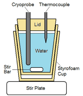
Figure 1. Illustration of the calorimetry testing fixture. The setup is designed to prevent ice formation on the probe surface during a freeze and allows for assessment of temperature change of water during a given freeze run. Time and temperature data are then utilized to calculate the cooling power of a given cryoprobe.
Cooling power was determined using standard calorimetry calculations.
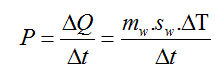
Where P=Cooling power, Q=Heat energy, mw=Mass of water, sw=Specific heat of water (4.186 J/g∙°C), T=Temperature, and t=Time (length of freeze procedure).
Freeze zone size and thermal profile assessment
Ice ball diameters: Partially Submerged Ablation Segment: An acrylic testing fixture (105 mm×125 mm×55 mm) was filled with room temperature (20±2°C) water, and the cryoprobe was laid horizontally on the surface (Figure 2). The probe height was adjusted such that half of the ablation segment probe (1 mm for HRS-1 and 1.7 mm for HRS-2) was submerged, and a 2 min freeze was performed. Following the freeze procedure, ice ball diameter was measured at the midpoint of the ablation segment. The time to first ice was also recorded. Fully Submerged Ablation Segment: Cryoprobes were placed vertically into the center of an acrylic testing fixture (51 mm×51 mm×200 mm) filled with room temperature (20±2°C) water to a level ∼10 mm above the proximal end of the freeze zone (Figure 3). A 2 min freeze was performed, and the ice ball diameter was measured at three locations: the distal end (15 mm from tip), the middle (50 mm from the tip), and the proximal end (85 mm from the tip).
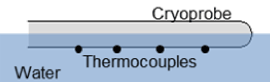
Figure 2. Illustration of the partially submerged cryocatheter testing setup. The fixture allows for visualization of iceball formation and measurement of overall freeze zone size during and following a given freeze interval. The thermocouple positioned on the exterior surface allows for assessment of probe surface temperature under various heat loads.
Thermal profile of freeze zone: Cryoprobe Surface Temperature: Cryoprobe external surface temperature assessment consisted of 10, 36 ga type-T thermocouples affixed in a straight line to the cryoprobe surface every 10 mm starting 5 mm from the distal end using fine cotton thread. The cryoprobe and thermocouple array was placed horizontally into an acrylic testing fixture (105 mm×125 mm×55 mm) filled with room temperature (20±2°C) water. The probe was adjusted such that half of the probe (1 mm for HRS-1 and 1.7 mm for HRS-2 and catheter) was submerged, and all of the thermocouples were at the bottom of the probe (submerged in the water) (Figure 2). A 3 min freeze was performed, and temperatures were recorded at a rate of 1/sec. Thermal Profiles of Ice Balls: The cryoprobe ablation segment was placed into the center of an acrylic testing fixture (51 mm×51 mm×200 mm) filled with room temperature (20±2°C) ultrasound gel to a level ∼10 mm above the proximal end of the probe freeze zone (Figure 3). A thermocouple mandrill consisting of 5, 36 ga type-T thermocouples soldered to a 22XT (0.7 mm OD) stainless steel tube was then placed at the midpoint of the freeze zone [53] The thermocouples and mandrill were situated such that temperature recordings were taken at 1 mm, 6 mm, 11 mm 13.5 mm and 16 mm extending radially from the cryoprobe surface. Temperatures were recorded at a rate of 1/sec, and all tests were run for 3 min.
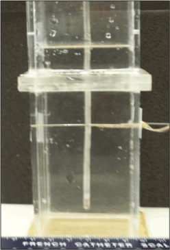
Figure 3. Image of the fully submerged isothermal profile assessment fixture. The fixture contains a water or ultrasound gel medium and a mandrel with thermocouples affixed at 5 pre-set distances allowing for real-time recording of a freeze run and determination of isotherm location at any point during a given freeze.
Freeze repeatability testing: For assessment of cryoprobe freeze repeatability, the cryoprobe was placed into a warm water bath and activated for 4 consecutive 15 or 30 second freezes with a 30 second thaw cycle between each freeze. As with thermal profile testing, probe surface temperature was monitored via a type t-thermocouple placed within the freeze chamber of the cryoprobe ablation segment.
Ex vivo tissue analogue testing
Ex vivo epicardial tissue model testing consisted of two setups, the first allowing for visualization of the iceball formation on the transmural surface of the tissue following a freeze procedure and the second allowing for thermal profiling of the tissue surface proximal and distal (transmural) to the cryoprobe.
Freeze zone transmurality visualization: For freeze zone visualization, a section of floral foam (phenolic foam), approximately 110 mm (L)×50 mm (W)×15 mm (D), was placed into a circulating 37°C water bath on a mesh platform and the foam height was adjusted such that the top of the foam was even with the water surface. A section of bovine skeletal muscle, approximately 100 mm (L)×45 mm (W)×4.5 – 5 mm (D), was then placed on top of the foam. The SCN cardiac cryoprobes were then laid atop the tissue section and a 2 min freeze was performed (Figure 4a). The water in the fixture was maintained at 37°C and was circulated at a rate of 4.5 L/min using a rotary pump during the freeze procedure. Immediately following the freeze, the floral foam was removed from the bath and the non-frozen portion was gently removed. The remaining foam (indicating the extent of the freeze zone) was allowed to dry prior to recording freeze zone measurements (Figure 4b)
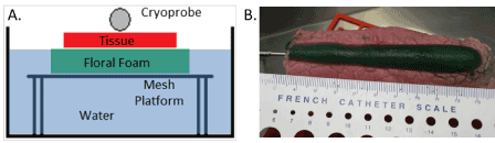
Figure 4. Illustration of the ex vivo heat loaded iceball transmurality analysis setup. A) Schematic of ex vivo heat load epicardial tissue model setup. The setup allows for analysis of the freeze zone formation within the tissue and foam following a freeze as well as the impact of a heat load on freeze formation. B) Photograph of the freeze zone created by the HRS1 cryoprobe in the floral foam on the opposite (transmural) surface of the tissue following a 2-minute freeze.
Epicardial analog thermal assessment: Assessment of the thermal profile within the tissue during the freeze interval was assessed using a similar setup to that of the freeze zone visualization. Specifically, an acrylic fixture (175 mm×140 mm×90 mm) with a suspended, vinyl polyester mesh platform (130 mm×90 mm) was filled with 37±2°C water to a level ∼1 mm above the mesh platform. The mesh platform contained a series of 5, type-T thermocouples integrated on the upper surface starting at the center and extending in a straight line perpendicular to the length. Thermocouples were positioned at 0 mm, 5 mm, 7.5 mm, 10 mm, and 15 mm from the center of the mesh (Figure 5). A section of bovine skeletal muscle, ∼100 mm×45 mm×4.5 – 5 mm, was placed on top of the mesh platform and the cryoprobe was then laid atop the tissue. The entire test fixture was placed on a scale and a standard downward probe tissue contact force of 50 g was applied by pressing the cryoprobe down on the tissue section using a vertical vice. Two, 190 g weights connected by polypropylene monofilament line were also draped across the distal end of the cryoprobe and the acrylic box to ensure consistent contact between the probe and the tissue which applied an additional force of 40 g, yielding a total probe/tissue surface contact force of ∼90 g. Once the setup was assembled, the water in the fixture was then maintained at 37°C and was circulated at a rate of 4.5 L/min using a rotary pump during the 3 min freeze procedure. A second series of tissue studies was also conducted using a 1 cm thick section of porcine muscle (∼100 mm×45 mm×10 mm).
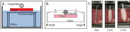
Figure 5. Illustration of the heat loaded ex vivo tissue isotherm assessment setup. A) Cross sectional schematic of the apparatus illustrating the probe and thermal sensors radiating perpendicular from the probe surface on the transmural (opposite) surface of the cardiac tissue section. The fixture allows for real-time assessment of thermal profiles within the tissue both on the proximal and transmural surface of the tissue section. B) Schematic illustration of the weighting setup utilized to provide a constant 90 g of down force on the cryoprobe during testing. C) Photographs of freeze zone created by the SCN cryoprobe during a freeze procedure in the ex vivo heat load model. Time lapse photos illustrate the frozen tissue area (white tissue) created around the cryoprobe following 1 and 2 minutes of freezing.
Data analysis
For calorimetry, iceball, thermal profile assessment and ex vivo tissue analog studies, a minimum of 3 repeats per probe were conducted. Following experimentation, data were combined and averaged (±SD) to determine mean iceball size, temperature location and ablation zone produced. Statistical significance was determined using single factor ANOVA where noted. Freeze zone size: Following the freeze/thaw episode, iceball diameter was measured using digital calipers at the center point of the cryoprobe freeze zone. Thermal Profiles: Real time recordings of the thermal profiles were collected using an Omega TempScan system and were converted to graphical format using Microsoft Excel and analyzed to determine isotherm spread during the freeze intervals. All temperatures were recorded at a rate of 1/sec.
Calorimetry testing
Evaluation of the epicardial cryoprobes cooling power was conducted using the calorimetry testing setup. Initial testing was conducted using a starting water temperature of 35°C. However, it was found that due to the increased cooling capacity of the SCN cryoprobe, this was not able to prevent ice formation on the surface of the cryoprobe regardless of the level of stirring of the water bath. Prevention of ice formation along the freeze zone during calorimetry testing is important, as ice along the probe shaft has an insulative effect, decreasing heat extraction capacity thereby yielding suppressed readings. As such, the water temperature was increased until minimal visual ice was apparent on the probe surface during the test run. This resulted in a final starting bath temperature of 85°C. Once the bath temperature was determined, calorimetric assessment of the cryoprobe was conducted (Table 1). Assessment of the 2 mm smooth surface HRS1- epicardial cryoprobe (2 mm×100 mm ablation segment) revealed an average decrease in temperature of 31°C (±2.7) during a 2 min freeze run, yielding an average cooling power of 327.7 W (±29.2). Assessment of the 3.4 mm diameter corrugated HRS-2 epicardial cryoprobe (3.4 mm×100 mm ablation segment) yielded an average decrease in temperature of 35.4°C (±1.6) yielding an average cooling power of 373.4 W (±17.2). The 14% increase in cooling power observed with HRS-2 vs. HRS-1 was attributed to the larger cryoprobe diameter (3.4 mm vs. 2.0 mm) and cooling surface configuration (corrugated vs. smooth), providing an increase in cooling surface area for the HRS-2 cryoprobe, yielding an increased cooling power.
Table 1. Assessment of cooling Power for SCN epicardial cardiac cryoprobes following a 2 min freeze
Probe |
Water Temperature (°C) |
Watts |
Start |
End |
DT |
HRS-1 |
85.1 |
54.1 |
31.0 |
327.7 |
HRS-2 |
86.4 |
51.0 |
35.4 |
373.5 |
Freeze zone size and thermal profile assessment
Freeze zone size: Evaluation of freeze zone (iceball) size was conducted using two heat load scenarios, partial and full cryoprobe freeze zone submersion. These paradigms were designed to evaluate the relative impact of increased heat load on cryoprobe performance. Analysis of time to initial ice formation (visualization of ice on the ablation segment) revealed no substantial difference between the partial and fully submerged protocol with the cryoprobe achieving initial ice formation in less than 3 seconds following activation (Table 2). Assessment of freeze zone size also revealed the attainment of a similar diameter which was consistent along the length of the cryoprobe freeze segment. Specifically, an average iceball diameter of ∼2.0 cm along the entire length was attained following a 2-minute freeze in both settings (Table 2).
Table 2. Ice kinetics of a partially and fully submerged cryoprobe following a 2 min freeze
Probe Submersion |
Probe (Dia) |
Time to Ice (sec) |
Ice Ball Dia. (cm) |
Tip |
Middle |
Base |
Partial |
HRS1 (2 mm) |
2.0 |
1.90 |
1.96 |
2.01 |
|
HRS2 (3.4 mm) |
1.5 |
1.92 |
2.13 |
2.13 |
Full |
HRS1 (2 mm) |
1.7 |
2.08 |
2.06 |
1.90 |
|
HRS2 (3.4 mm) |
1.3 |
2.27 |
2.26 |
2.14 |
Thermal profile of freeze zone: Following establishment of freeze zone size, analysis of the thermal profile within the iceball was conducted. This included assessment of ablation segment surface temperature along the entire surface of the cryoprobe as well as monitoring temperature distribution outward from the probe surface. Analysis of cryoprobe surface temperatures recorded at 5 mm intervals along the probe freeze segment revealed the attainment of a consistent average temperature of -140°C on the external probe surface when assessed using both the partial and full submersion water bath models (Table 3). Importantly, a probe surface temperature of -100°C was attained within 13 (±2) seconds of probe activation along the entire surface of both probe types.
Table 3. Thermal profile of a partially submerged cryoprobe
Probe Type |
Time to Ice (sec) |
Nadir External Surface Temp. (°C) (location measured from distal end of probe) |
5 mm |
15 mm |
25 mm |
35 mm |
45 mm |
55 mm |
65 mm |
75 mm |
85 mm |
95 mm |
HRS1 |
1.5 |
-140.0 |
-140.4 |
-143.1 |
-143.1 |
-140.0 |
-137.3 |
-139.7 |
-143.9 |
-145.5 |
-145.8 |
HRS2 |
1.3 |
-112.0 |
-141.6 |
-138.4 |
-141.3 |
-137.4 |
-134.7 |
-137.2 |
-139.2 |
-144.7 |
-139.4 |
For determination of isothermal distribution from the probe surface, temperatures were recorded in real time at 1 sec intervals on the probe surface, 1, 6, 11, 13.5 and 16 mm radially from the probe during a 3 min freeze (Figure 6). Following completion of the freeze, the depth of penetration of the -20°C, -30°C and -40°C critical isotherms was determined (Table 4). Analysis of the isothermal distribution within the frozen mass revealed that the -20°C isotherm extended 1.1 cm from the cryoprobe surface (diameter=2.2 cm), the -30°C isotherm extended 1.05 cm (dia=2.1 cm), and the -40°C isotherm extended 0.95 cm from the surface (dia=1.9 cm) following a 3 min freeze interval (Table 4). Volumetric analyses for the frozen region, assuming a cylindrical shape, following a 2 min or 3 min freeze interval revealed a total frozen mass of 31.4 cm3 and 42.6 cm3 for HRS1 and 38.1 cm3 and 46.0 cm3 for HRS2, respectively. Calculating the volume of ice contained at or below each critical isotherm revealed that for HRS1, 92% (39.4 cm3) of the total frozen volume was below -20°C, 84% (35.8 cm3) below -30°C and 73% (31.1 cm3) below -40°C. Similar results were found with the corrugated HRS2 cryoprobe where isotherm volume analysis revealed that 93% (42.8 cm3) was below -20°C, 79% (36.2 cm3) below -30°C and 63% (28.9 cm3) below -40°C.
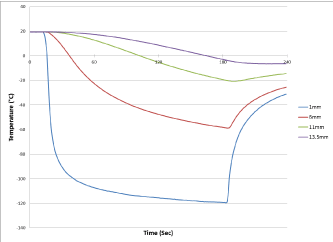
Figure 6. Real-time monitoring of the isothermal profile generated by the SCN cryoprobe at the center of the ablation segment during a 3-minute freezing protocol. Temperatures of the mid-point of the freeze zone were monitored at fixed points radiating from the HRS-2 cryoprobe surface in real –time at 1 second intervals during a 3-minute freeze procedure. Temperatures were found to drop quickly near the probe surface and more gradually the further from the probe surface. Thermal profile assessment revealed a final penetration of the -20°C, -30°C and -40°C isotherms to reach diameter of 2.2 cm, 2.1 cm and 1.9 cm, respectively, on average. Analysis of the thermal profiles revealed that approximately 90% and 65% of the frozen mass was encompassed by the -20°C and -40°C isotherms, respectively, for the two cryoprobe designs.
Table 4. Assessment of the penetration of critical isotherms of a fully submerged cryoprobe
Probe Type |
Probe Freeze Zone
(mm) |
Time to Ice
(sec) |
Time to -100°C
(sec) |
Ice Ball Dia. (cm) |
Isotherm Dia. at 3 min (cm) |
2 min |
3 min |
-20°C |
-30°C |
-40°C |
HRS1 |
2.0 x 100 mm |
2.0 |
10 |
2.00 |
2.33 |
2.24 |
2.14 |
1.99 |
HRS2 |
3.4 x 100 mm |
2.0 |
12 |
2.20 |
2.42 |
2.34 |
2.15 |
1.92 |
Freeze repeatability testing: One critical aspect of device performance for application in a cardiac setting is that of quick and consistent application of freeze ablation. To test the utility of the SCN cryoprobes under this scenario, a repeat freeze challenge model was applied. To this end, the cryoprobe was placed into a heated water bath (30°C) and cryogen flow was cycled for 4 consecutive freezes of 30 seconds with a 30 second pause between each freeze. Probe surface temperature was monitored throughout the cycling process. Additionally, time to nadir temperature and the ability to return to starting temperature within the thaw window was also monitored (Figure 7). Cycling analysis revealed that the epicardial SCN cryoprobe was able to rapidly and repeatedly achieve a nadir probe surface temperature of below -100°C (±2°C) within 10 (±2) seconds and < -140°C (±3) in 20 (±4) seconds following the initial freeze and was able to return to starting temperature (thermal rebound) following ending of cryogen flow within 15 (±2) seconds. Importantly, upon stopping of cryogen flow, the probe started warming in <2 seconds, warming to above -20°C within 7 (±1) seconds demonstrating, rapid and repeatable on/off control of freezing.
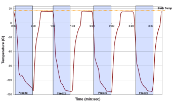
Figure 7. Thermal profiles of the SCN cryoprobe during repeated 30 sec freeze cycling. The HRS1 cryoprobe (2.0 mm x 100 mm) freeze zone was placed into a warm water bath and repeatedly activated for 30 sec freeze intervals with a 30 sec thaw between each of the 4 cycles. The cryoprobe (entire freeze zone submerged) yielded a thermal profile of ice formation in <5 sec and achieved a temperature of below -125°C (±4°C) within 10 sec.
Ex vivo tissue analogue testing
Endocardial analog testing: With establishment of the freeze zone dimensions following a 2 min and 3 min freeze in a partial heat load model, two heat loaded tissue models were utilized to assess cryoprobe performance under full heat load. The first model was used to visualize transmural freeze lesion creation. To this end, a 4.8 mm (±0.1) thick slice of bovine cardiac tissue was placed on top of a section of floral foam which was submerged in a circulating (4.5 L/min) 37°C water bath. The cryoprobe was placed on top of the tissue surface and a total probe/tissue surface contact force of ∼90 g was applied (Figure 4) Following a 2 minute freeze interval, the iceball diameter at the probe/tissue interface was measured and then the tissue was removed and the frozen floral foam was extracted from the non-frozen foam, allowed to dry and then the foam cast of the transmural iceball was measured at three locations along the probe surface (Figure 4b). These analyses demonstrated the ability of both cryoprobe configurations (HRS1=2 mm smooth surface and HRS2=3.4 mm corrugated surface) to create an iceball on the opposite surface of the tissue in the circulating heat loaded model (Table 5).
Table 5. Freeze zone created by the SCN epicardial cryoprobes in an epicardial tissue analog
Probe (dia) |
Tissue Thickness (mm) |
Ice Ball Diameter (cm) |
Foam Dimensions (cm) |
Tip |
Middle |
Base |
Width |
Depth |
Width |
Depth |
Width |
Depth |
HRS1 (2.0 mm) |
4.8 |
1.69 |
1.37 |
0.40 |
1.20 |
0.36 |
1.05 |
0.26 |
HRS2 (3.4 mm) |
4.8 |
2.05 |
1.56 |
0.45 |
1.53 |
0.43 |
1.54 |
0.48 |
Following establishment of opposite surface iceball creation, studies were conducted to determine the temperature profile attained within the tissue on both the adjacent and opposite surfaces of the tissue during a freeze protocol. In this model, the opposite surface of the tissue was directly exposed to the circulating bath heat load (37°C water circulating at 4.5 L/min). For this assessment, a mesh platform containing an array of thermocouples radiating perpendicular to the ablation segment position was placed within the circulating bath, the tissue placed on top of the mesh platform and then the cryoprobe placed on the upper surface of the tissue with 90 g of down force applied to the probe. This setup allowed for thermal profile monitoring on the opposite tissue surface which was directly in the flow of the heated circulating bath throughout the freeze process (Figure 8) Analysis revealed the creation of a uniform 1.9 (±0.1) cm diameter freeze zone on the opposite/transmural surface (endocardial surface equivalent) of a 4.5 mm thick tissue section along the entire probe freeze length following a 3 min freeze under full heat load with the opposite (transmural) tissue directly in the heated circulating flow path using either of the SCN cryoprobes. Analyses of the thermal profile of the opposite/ transmural (endocardial) surface revealed that a temperature of 0°C was achieved in ∼15 sec, -20°C in ∼20 sec, and -30°C within 30 sec directly below the probe tissue interface (Table 6) The nadir transmural tissue surface temperature recorded was between -60°C and -55°C (±2°C) for both probe configurations under the full circulation heat load. The thermal spread of the ablation zone revealed the temperature 5 mm perpendicular to the center line of the freeze zone on the opposite (transmural) tissue surface when the transmural 0 mm position (directly below the ablation segment in the flow path) reached -30°C, was 30°C for HRS1 and 14°C for the larger HRS2 cryoprobe. These data suggested that the SCN cryoprobe was able to deliver a precise ablative thermal dose of -30°C across a 5 mm tissue segment under full heat load in ∼30 sec while resulting in minimal unwanted destructive thermal spread within the tissue.
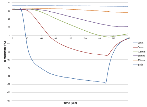
Figure 8. Real-time monitoring of the isothermal profile generated on the transmural tissue surface by the SCN cryoprobe in the heat load ex vivo bovine tissue model. During a 3 Minute Freezing Protocol. Temperatures of the mid-point of the freeze zone were monitored at fixed points radiating from the cryoprobe surface on the distal (endocardial) tissue surface. Temperatures were recorded in real –time at 1 second intervals during a 3-minute freeze procedure. Temperatures on the distal surface (endocardial) decreased rapidly directly below the cryoprobe achieving <-30°C across the entire tissue thickness within 30 seconds and a nadir temperature of <-50°C on the distal surface despite being exposed to 37°C water circulating across the surface at a rate of 4.5L/min throughout the 3 min freeze interval.
Table 6. Thermal profile of the cryoprobe on the heat loaded circulating epicardial tissue analog
Probe Type |
Tissue Thickness
(mm) |
Time to Ice
(sec) |
Ice Ball Diameter (cm) |
Time to Transmural Temp. (sec) |
Nadir Transmural
Temp. (°C) |
Thermal Spread
at 5 mm (°C) |
Tip |
Middle |
Base |
0 °C |
-20 °C |
-30 °C |
HRS1 |
4.5 |
1.7 |
1.94 |
1.96 |
1.91 |
12.3 |
19.7 |
21.5 |
-60.5 |
30.7 |
HRS2 |
4.5 |
2.3 |
2.09 |
2.07 |
2.07 |
16.3 |
22.3 |
28.3 |
-54.7 |
14.2 |
Ablative devices typically undergo extensive bench and ex vivo testing and characterization with the majority of published studies detailing animal models or clinical studies and focus on acute, mid and long term clinical outcome. While important, outcome is dictated by device performance, tissue thickness, tissue contact, final temperature attained throughout the tissue, time of application, time necessary to reach a given temperature and impact of heat load (blood flow), among others. To this end, most of published information pertaining to device performance is restricted to probe temperature (typically measured at some point within the cryogen flow path) and time of application. This is unfortunate, as it does not provide a body of comparative data for clinicians, researchers and engineers to draw upon to further understand device performance and thereby limits the ability for optimization of procedures and device design. Further, it makes comparison of current devices and the development of new devices challenging. As such, the use of ex vivo models to assess the performance characteristics of thermal ablation devices, such as cryoablation devices and probes, is important. Serving as a comparative standard, studies have also shown that the depth of penetration of the critical -20°C and -40°C isotherms is an important indicator of ablative success both ex vivo and in vitro (24,53-55,59,62,65,66) While serving as a good comparative standard, the model in which the isotherm penetration is assessed can significantly impact results. For example, at a given temperature, agarose and ultrasound gel models provide for more favorable isotherm penetration than water baths. Further, the volume of the assessment medium (heat load) also impacts outcome, especially with extended freeze times of 10 to 20 mins, as in the smaller volume fixtures, the entire apparatus can be cooled as no consistent external heat source is provided. Finally, in cardiac settings, flow vs static models can also yield highly differing results. It is important to understand the model utilized and recognize the benefits and limitations in order to frame the results. Several studies have shown that the distribution of the -20°C and -40°C critical isotherms is often restricted to the center of the frozen mass (closest to the cryoprobe), thereby comprising less than 35% and 20% of the frozen mass, respectively (53-55,58,61,67) The typical freeze times reported in these and other studies range from 5 to 10 minutes which are applied in multiple (repeat) freeze/thaw scenarios. While limited, these data provide a reference point for comparison of modern technologies. One important conclusion from these studies is the need for the development of new devices which provide increased cryoablative capacity which in turn could improve outcome while reducing procedure time. A new cryoablation probe, which utilizes SCN, designed to deliver a rapid, controlled ultra-cold ablative dose to a target region has been developed. Due to the increased heat extraction capability of SCN compared to argon and nitrous oxide cryogens, SCN also offers the potential to deliver ablative doses deep into tissue while exposed to high heat loads, such as blood flow in a fully beating heart (58,61,62) In this study we utilized a series of ex vivo models to assess and characterize system performance. Further, these studies were also designed to describe a series of bench testing model systems which could potentially serve as reference standards for pre-clinical and clinical study development and protocol optimization.
In this study we examined the performance of a new SCN-based epicardial cryoablation probe platform. Analysis of cryoprobe performance included calorimetry (ablative energy), freeze zone (ice ball) size under various heat loads, thermal profiling of the frozen mass in phantom models and the impact of high heat load (37°C water) circulating flow on lesion formation in an ex vivo tissue model. Calorimetric assessment demonstrated that the epicardial SCN cryoprobes yielded an average cooling power greater then 325 W. Cooling power (wattage) is not typically reported for cryoablation probes. However, available information suggests that current argon and nitrous oxide cryoprobes provide a range of 50 to 90 W of cooling power, depending on the probe type and configuration (i.e. needle vs. catheter vs. surgical probe) with the larger probe freeze zones providing a greater cooling power. Assessment of freeze zone formation revealed the formation of a ∼2 cm diameter iceball in 2 minutes and 2.3 cm in 3 mins with the epicardial SCN cryoprobe in both a partial and fully submerged water bath model (Tables 2 and 3, Figure 6). Isothermal profiling of the frozen mass created by the epicardial cryoprobes revealed penetration of the -20°C, -30°C and -40°C isotherms to a diameter of 2.2 cm, 2.1 cm and 1.9 cm in a 2.3 cm iceball following a 3 minute freeze resulting in ∼90% of the frozen volume below -20°C, 80% below -30°C and >65% below -40°C for the various SCN epicardial cryoprobe configurations (Table 4). This significantly outperformed previous reports on an argon cryodevice which was reported to yield ∼35% and ∼20% of the iceball being below -20°C and -40°C, respectively [53,61]. Other studies focusing on analysis of the -30°C isotherm have reported that an argon based cryoprobe produces ∼25% of the frozen mass under -30°C under similar conditions [54,55]. In comparing the SCN cryoprobe data to the literature, our data suggest that the SCN cryoprobe creates a substantially colder frozen mass more rapidly in comparison to other cryoablation systems. Importantly, it was found that even under the extremely challenging ex vivo 37°C circulating flow epicardial tissue model, the SCN cryoprobes were able to generate lesions with the penetration of the critical -20°C and -30°C isotherms through the full thickness of the tissue model within 20 and 30 seconds, respectively (Table 6, Figure 8) and with precise control (Figure 7).
As the use of cryotherapy continues to grow for the treatment of cardiac arrhythmias, future improvements to device design are needed to achieve effective ablation in a minimally invasive, time efficient manner. In this study we investigated the application of a SCN cryoprobe for the epicardial cryoablation of cardiac tissue. The data presented herein suggests that the SCN epicardial cryoprobe provides for the rapid delivery of an effective cryoablative dose to the target tissue using the ex vivo models evaluated. The data demonstrate that the delivery of a “thermal dose” of -30°C [59,60-68] across tissue ranging from 5 mm to 1 cm in thickness under high (37°C) circulating heat loads in less than 2 minutes. Analysis of the thermal spread of the lethal temperatures during a 2-minute freeze was limited to within 5 mm of the probe surface thereby resulting in the creation of a defined linear ablation zone. While not described herein, preliminary in vivo studies currently under way further support these findings. These studies demonstrate that the SCN epicardial cryoprobe can rapidly create a precise linear transmural lesion resulting in electrical conduction block following freeze intervals of 30-90 seconds (tissue thickness dependent) in cardiac tissue in fully beating hearts (no bypass).
In conclusion, our findings suggest that the SCN system offers promise as a next generation cryoablation device for the epicardial based treatment of various cardiac arrhythmias. Our findings also suggest that the SCN technology may provide a path for the use of cryoablation in areas which have traditionally challenged cryoablation, such as for the treatment of ventricular tachyarrhythmias via a modified Cryomaze approach. While the results of this study are promising, given their investigational nature, the extent of conclusions which can be drawn is limited; however, the data does suggest that this technology holds promise and that continued assessment of the technology in vivo is warranted.
Availability of data and material:
Competing interests: JMB, AR, KKS and RVB are employees of CPSI Biotech. JGB has no competing interests. All authors are named inventors on patents related to the cryoablation technologies evaluated under this study.
Funding: This study was supported in part by funding from the National Institutes of Health and CPSI Biotech.
Authors' contributions: JMB, AR and KKS performed all experimental design, experimentation and data analysis for this study. RVB and JGB conducted data and experimental design review and assisted in data interpretation. JMB prepared the draft manuscript. AR, KKS, RVB and JGB provided review and revision input for the manuscript. All authors read and approved the final manuscript.
Acknowledgements: The authors would like to thank Dr. Kimberly Santucci for her technical assistance in preparing this manuscript.
- Wattigney WA, Menasah GA, Croft JB (2003) Increasing trends in hospitalization for atrial fibrillation in the United States, 1985 through 1999. Implication for primary prevention. Circulation 108: 711. [Crossref]
- Ryan SS (2002) Atrial Fibrillation Resources for Patients.
- Miyasaka W, Barnes ME, Gersh BJ, Cha SS, Bailey KR, et al. (2006) Secular trends in incidence of atrial fibrillation in Olmsted County, Minnesota, 1980-2000, and implications on the projections for future prevalence. Circulation 114: 119.
- Roy D, Talajic M, Dubuc M, Thibault B, Guerra P, et al. (2009) Atrial fibrillation and congestive heart failure. Curr Opin Cardiol 24: 29-34. [Crossref]
- Wyndham CR (2000) Atrial fibrillation: the most common arrhythmia. Tex Heart Inst J 27: 257-267. [Crossref]
- Mathew J, Hunsberger S, Fleg J, Mc Sherry F, Williford W, et al. (2000) Incidence, predictive factors, and prognostic significance of supraventricular tachyarrhythmias in congestive heart failure. Chest 118: 914-22.
- Zareba W, Steinberg JS, McNitt S, Daubert JP, Piotrowicz K, et al. (2006) Implantable cardioverter-defibrillator therapy and risk of congestive heart failure or death in MADIT II patients with atrial fibrillation. Heart Rhythm 3: 631-637. [Crossref]
- Mazzini MJ, Monahan KM (2008) Pharmacotherapy for atrial arrhythmias: present and future. Heart Rhythm 5: S26-S31.
- Novak PG (2009) Effectiveness of catheter ablation versus antiarrhythmic drug therapy for atrial fibrillation. Curr Opin Cardiol 24: 9-17.
- Ehrlich JR, Nattel S (2009) Atrial-selective pharmacological therapy for atrial fibrillation: hype or hope? Curr Opin Cardiol 24: 50-55. [Crossref]
- Parvez B, Pathak V, Schubert CM, Wood M (2008) Comparison of lesion sizes produced by cryoablation and open irrigation radiofrequency ablation catheters. J Cardiovasc Electrophysiol 19: 528-34.
- Wright M, Sacher F, Haďssaguerre M (2009) Catheter ablation for patients with ventricular fibrillation. Curr Opin Cardiol 24: 56-60. [Crossref]
- Chanani NK, Chiesa NA, Dubin AM, Avasarala K, Van Hare GF, et al. (2008) Cryoablation for atrioventricular nodal reentrant tachycardia in young patients: predictors of recurrence. Pacing Clin Electrophysiol 31: 1152-1159.
- Avari JN, Jay KS, Rhee EK (2008) Experience and results during transition from radiofrequency ablation to cryoablation for treatment of pediatric atrioventricular nodal reentrant tachycardia. Pacing Clin Electrophysiol 31: 454-460.
- Chun KR, Schmidt B, Kokturk B, Tilz R, Furnkranz A, et al. (2008) Catheter ablation - new developments in robotics. Herz 33: 586-589.
- McKenna C, Palmer S, Rodgers M, Chambers D, Hawkins N, et al. (2008) Cost-effectiveness of radiofrequency catheter ablation for the treatment of atrial fibrillation in the UK. Heart.
- Cappato R, Calkins H, Chen SA, Davies W, Iesaka Y, et al. (2005) Worldwide survey on the methods, efficacy, and safety of catheter ablation for human atrial fibrillation. Circulation 111: 1100-1105.
- Babaian RJ, Donnelly B, Bahn D, Baust JG, Dineen M, et al. (2008) Best Practice Statement on Cryosurgery for the Treatment of Localized Prostate Cancer. J Urol 180: 1993-2004. [Crossref]
- Cohen JK, Miller RJ Jr, Ahmed S, Lotz MJ, Baust J (2008) Ten-year biochemical disease control for patients with prostate cancer treated with cryosurgery as primary therapy. Urology 71: 515-518 .
- Baust JG, Gage AA, Robilottto AT, Baust JM (2009) The pathophysiology of thermoablation: optimizing cryoablation. Curr Opin Urol 19: 127-132. [Crossref]
- Baust JG, Gage AA, Clarke D, Baust JM, Van Buskirk R (2004) Cryosurgery--a putative approach to molecular-based optimization. Cryobiology 48: 190-204.
- Gage AA, Baust JG (2004) Cryosurgery for tumors - a clinical overview. Technol Cancer Res Treat 3: 187-199. [Crossref]
- Baust JG, Gage AA, Klossner D, Clarke D, Miller R, et al. (2007) Issues critical to the successful application of cryosurgical ablation of the prostate. Technol Cancer Res Treat 6: 97-109.
- Gage AA, Snyder KK, Baust JM, Baust JG (2008) The Principles of Cryobiology. In: Dubac, M. and Khairy, P. editors. Cryoablation for Cardiac Arrhythmias. Quebec, Canada: Vision Commun 2008: 3-12.
- Baust JG, Gage AA (2004) Progress toward optimization of cryosurgery. Technol Cancer Res Treat 3: 95-101.
- Baust JM, Mathew AJ, Snyder KK, Liu EH, Van Buskirk RG, et al. (2004) Transplantation Diagnostics: A Preliminary Analysis Using Protein Microarray to Determine Kidney Status Prior To and Following Implantation. Cell Preservation Technology 2: 81-90.
- White RL Jr (2008) Cryoablative therapy in breast cancer: no. J Surg Oncol 97: 483-484. [Crossref]
- Sabel MS (2008) Cryoablation for breast cancer: no need to turn a cold shoulder. J Surg Oncol 97: 485-486. [Crossref]
- Baust JG, Gage AA (2005) The molecular basis of cryosurgery. BJU Int 95: 1187-1191. [Crossref]
- Gage AA, Baust JG (2007) Cryosurgery for tumors. J Am Coll Surg 205: 342-356. [Crossref]
- Clarke DM, Robilotto AT, VanBuskirk RG, Baust JG, Gage AA, et al. (2007) Targeted induction of apoptosis via TRAIL and cryoablation: a novel strategy for the treatment of prostate cancer. Prostate Cancer Prostatic Dis 10: 175-184. [Crossref]
- Ellis DS, Manny TB Jr, Rewcastle JC (2007) Focal cryosurgery followed by penile rehabilitation as primary treatment for localized prostate cancer: initial results. Urology 70: 9-15.
- Mayes JM, Mouraviev V, Polascik TJ (2008) Impact of a cryotherapy training workshop on the adoption and utilization of cryotherapy in the community setting. Can J Urol 15: 4147-4152.
- Jones JS, Rewcastle JC, Donnelly BJ, Lugnani FM, Pisters LL, et al. (2008) Whole gland primary prostate cryoablation: initial results from the cryo on-line data registry. J Urol 180: 554-558. [Crossref]
- Bahn DK, Silverman PD (2008) Focal cryoablation of prostate: a review. ScientificWorldJournal 8: 486-491. [Crossref]
- Bandi G, Hedican SP, Nakada SY (2008) Current practice patterns in the use of ablation technology for the management of small renal masses at academic centers in the United States. Urology 71: 113-117. [Crossref]
- Ramírez ML, Evans CP (2007) Current management of small renal masses. Can J Urol 14 Suppl 1: 39-47. [Crossref]
- Maiwand MO, Asimakopoulos G (2004) Cryosurgery for lung cancer: clinical results and technical aspects. Technol Cancer Res Treat 3: 143-150. [Crossref]
- Baust JG (2002) Cryotherapeutic Intervention in Cardiovascular Disease. Institute of Biotechnology, SUNY.
- Masroor S, Jahnke ME, Carlisle A, Cartier C, Lalonde JP, et al. (2008) Endocardial hypothermia and pulmonary vein isolation with epicardial cryoablation in a porcine beating-heart model. J Thorac Cardiovasc Surg 135: 1327-1333. [Crossref]
- Gage AA, Baust JM, Baust JG (2007) Principles of Cryosurgery. In: Rukstalis, D. editor. Handbook of Urological Cryoablation. Abington, UK: Informa Healthcare.
- Rukstalis DB, Goldknopf JL, Crowley EM, Garcia FU (2002) Prostate cryoablation: a scientific rationale for future modifications. Urology 60: 19-25. [Crossref]
- Ladd AP, Rescorla FJ, Baust JG, Callahan M, Davis M, et al. (1999) Cryosurgical effects on growing vessels. Am Surg 65: 677-682. [Crossref]
- Cox JL, Boineau JP, Schuessler RB, Jaquiss RD, Lappas DG (1995) Modification of the maze procedure for atrial flutter and atrial fibrillation. I. Rationale and surgical results. J Thorac Cardiovasc Surg 110: 473-484. [Crossref]
- Cox JL, Ad N (2000) The importance of cryoablation of the coronary sinus during the Maze procedure. Semin Thorac Cardiovasc Surg 12: 20-24. [Crossref]
- Gaita F, Gallotti R, Calo L, Manasse E, Riccardi R, et al. (2000) Limited posterior left atrial cryoablation in patients with chronic atrial fibrillation undergoing valvular heart sugery. J Am Coll Cardiol 36: 159-166. [Crossref]
- Baust JM, Van Buskirk R, Baust JG (2002) Modulation of the cryopreservation cap: elevated survival with reduced dimethyl sulfoxide concentration. Cryobiology 45: 97-108. [Crossref]
- Dubuc M, Talajic M, Roy D, Thibault B, Leung TK, et al. (1998) Feasibility of cardiac cryoablation using a transvenous steerable electrode catheter. J Interv Card Electrophysiol 2: 285-292. [Crossref]
- Dubuc M, Khairy P, Rodriguez-Santiago A, Talajic M, Tardif JC, et al. (2001) Catheter cryoablation of the atrioventricular node in patients with atrial fibrillation: a novel technology for ablation of cardiac arrhythmias. J Cardiovasc Electophhysiol 12: 439-444. [Crossref]
- Gaita F, Haissaguerre M, Giustetto C, Grossi S, Caruzzo E, et al. (2003) Safety and efficacy of cryoablation of accessory pathways adjacent to the normal conduction system. J Cardiovasc Electrophysiol 14: 825-829. [Crossref]
- Rodriguez LM, Timmermans C (2004) Transvenous cryoablation of cardiac arrhythmias. Technol Cancer Res Treat 3: 515-524. [Crossref]
- Reek S, Geller JC, Schildhaus HV, Ripley KL, Klein HU (2004) Feasibility of catheter cryoablation in normal ventricular myocardium and healed myocardial infarction. Pacing Clin Electrophysiol 27: 1530-1539. [Crossref]
- Baust JM, Robilotto AT, Snyder KK, Santucci KL, McKain J, et al. (2017) Assessment of Cryosurgical Device Performance Using an In Vivo-Like 3-D Tissue Engineered Cancer Model. Technol Cancer Res Treat.
- Littrup PJ, Jallad B, Vorugu V, Littrup G, Currier B, et al. (2009) Lethal isotherms of cryoablation in a phantom study: effects of heat load, probe size, and number. J Vasc Interv Radiol 20: 1343-1351. [Crossref]
- Shah T, Arbel U, Foss S, Zachman A, Rodney A, et al. (2016) Modeling Cryotherapy Ice Ball Dimensions and Isotherms in a Novel Gel-based Model to Determine Optimal Cryo-needle Configurations and Settings for Potential Use in Clinical Practice. Urology 91: 234-240. [Crossref]
- Kettering K, Al-Ghobainy R, Wehrmann M, Vonthein R, Mewis C (2006) Atrial linear lesions: feasibility using cryoablation. Pacing Clin Electrophysiol 29: 283-289. [Crossref]
- Lustgarten DL, Bell S, Hardin N, Calame J, Spector PS (2005) Safety and efficacy of epicardial cryoablation in a canine model. Heart Rhythm 2: 82-90. [Crossref]
- Baust JM, Robilotto AT, Gage AA, Baust JG (2016) Enhanced Cryoablative Methodologies. In: Bischof JCaX, Y, editor. Multiscale Technologies for Cryomedicine: World Scientific Publishing Co, pp: 388.
- Baust JG, Sanghvi NK, Snyder KK, Baust JM (2011) Mechanisms and application of cardiac cryoablation. EP Lab Digest 11.
- Snyder KK, Baust JM, Van Buskirk RG, Baust JG (2007) Cardiomyocyte Responses to Thermal Excursions: Implications for Electrophysiological Cardiac Mapping. Cell Preservation Technology 5: 116-28.
- Baust JM, Snyder KK, Santucci KL, Robilitto AT, Smith JT, et al. (2014) Assessment of SCN and argon cryoablation devices in an in vivo like 3-D tissue engineered prostate and renal cancer model. Poster session presented at ACCryo 2014-Advances in Thermal Abaltive Therapy and Biopreservation, Annual Meeting of the American College of Cryosurgery, Key Largo, FL.
- Baust JM RA, Lueckge C, Guerra P, Snyder KK, Cheeks R, et al. (2010) Development of a novel cryoablation device for the treatment of cardiac tachyarrhythmias. Hearth Rhythm, Denver, CO.
- Baust JM, Robilotto AT, Stewart JF, Snyder KK, Van Buskirk RG, et al. (2016) Development of a next generation cryoablation platform for the treatment of cardiac arrhythmias. Cryo2016- Cool developments in cryomedicine - New devices and strategies, Ottawa, Canada.
- Robilitto AT, Baust JM, Stewart JF, Van Buskirk RG, Baust JG, et al. (2016) Cryosurgical ablation in the gastrointestinal tract: development of a novel cryosurgical platform. Cryo2016-Cool developments in cryomedicine - New devices and strategies, Ottawa, Canada.
- Aliot EM, Stevenson WG, Almendral-Garrote JM, Bogun F, Calkins CH, et al. (2009) EHRA/HRS Expert Consensus on Catheter Ablation of Ventricular Arrhythmias: developed in a partnership with the European Heart Rhythm Association (EHRA), a Registered Branch of the European Society of Cardiology (ESC), and the Heart Rhythm Society (HRS); in collaboration with the American College of Cardiology (ACC) and the American Heart Association (AHA). Heart Rhythm 6: 886-933. [Crossref]
- Hai JJ, Tse HF (2013) Biophysical Principles and Properties of Cryoablation. The Practice of Catheter Cryoablation for Cardiac Arrhythmias: John Wiley & Sons, Ltd, pp: 1-7.
- Baust JM, Klossner DP, Robilotto A, Vanbuskirk RG, Gage AA, et al. (2012) Vitamin D (3) cryosensitization increases prostate cancer susceptibility to cryoablation via mitochondrial-mediated apoptosis and necrosis. BJU Int 109: 949-958.
- Snyder KK, Baust JG, Baust JM, Gage AA (2011) Mechanisms of Cryoablation. In: Bredikis AJ WD, editor. Cryoablation of Cardiac Arrhythmias. St Louis: W.B. Saunders, pp: 13-21.