Due to the high level of radiation generated by a spallation source, the construction of an effective shielding is necessary for radiation protection purposes. Neutron dose measurements and calculations around spallation sources are of great importance for an appropriate shielding study. Calculations of the spallation neutron attenuation by various shielding materials using a phenomenological model are presented. The calculations were compared with measurements using Solid State Nuclear Track (SSNTDs) as particle and fission detectors.
Spallation is an efficient endothermal process releasing neutrons from nuclei. To sustain a spallation reaction, an energetic beam of particles, most commonly protons must be supplied onto a heavy target. Spallation is a reaction which leads to only one heavy fragment whose mass is close to the target mass AT and a lot of light particles, such as neutrons, protons, deuterons etc. High energy reactions as spallation can play an important role as a source of neutrons whose flux can be easily controlled via the driving beam. The neutron spectrum of a spallation source in general is a continuous spectrum from intermediate up to the beam energy neutrons [1]. Due to the high level of radiation generated, the construction of an effective shielding is necessary for radiation protection purposes. In the current work calculations of the spallation neutron attenuation by various shielding materials were performed, using a phenomenological model, based on Moyer model [2,3]. The calculations were compared with measurements using Solid State Nuclear Track Detectors (SSNTDs) as particle and fission detectors [3,4]. Two different spallation sources were designed, and their neutron production was investigated during this work. The experiments were performed in Nuclotron accelerator at the Laboratory of High Energy of the Joint Institute for Nuclear Research (JINR), in Dubna, Russia [5,6].
The cost of the shielding contributes to a considerable part of the total financial cost of a spallation source, since massive shield materials should be used for strongly penetrating radiations. Consequently, calculations have to be performed before the construction of the shielding, while measurements are rarely presented in the literature. The calculations of the spallation neutron spectrum behind a shielding material can be implemented using analytical codes, Monte Carlo simulations or phenomenological models. The advantage of the phenomenological models is that the parameters needed for the calculation can be fixed, based on experimental results. Some codes specialized in shielding calculations are based on equations used in phenomenological models. The calculations based on phenomenological models in the case of shielding compare favorably with the Monte Carlo simulations. Comparison between measurements and calculations are presented.
The aim of this work is to study an appropriate shielding to surround two different spallation sources. In one spallation source, “Gamma-2” set-up, consisted by a Pb target covered by paraffin moderator and irradiated by protons at the GeV range. The Lead target was cylindrical with 8 cm diameter and 20 cm length surrounded by a cylindrical paraffin moderator, 6 cm in thickness and opened from the beam side [3,5] In the other set-up, “Energy plus Transmutation” (E+T), the Pb target was covered by four-sections of natural Uranium blanket and irradiated by protons with energy from 0.7 up to 2 GeV [3,5]. For radiation protection reasons 26 cm of polyethylene and 1 mm thickness of Cd surrounded the (E+T) spallation source. The experimental hall was shielded by 1 m Iron enriched concrete. The spallation sources were positioned in the middle of the experimental hall, approximately 3m from the concrete. The measurements and calculations have been performed behind the concrete [4]. Both spallation neutron sources were irradiated in Nuclotron accelerator, at the High Energy Laboratory (JINR), Dubna.
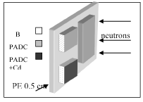
The neutron ambient dose equivalent behind the shielding of the two spallation sources was measured using (SSNTDs). Each set of detectors contained polly-allyl diglycol carbonate (PADC) foils (Pershore Mouldings standard grade, PM355) acting as a particle detector (Figure 1). Details on the detection methodology are given in the Ref 3 and 4. SSNTDs were also used as fission detectors. The fissioning targets, about 100 μg/cm2 in thickness, were evaporated on Makrofol foils. Targets of 235U and 232Th were used in order to study the slow and the fast component (above 2 MeV) of the neutron spectrum [7].

Figure 1. Design of the SSNTDs arrangement for neutron measurements.
CR39 used as light particle detector was calibrated with known neutron doses in the frame of EURADOS actions on neutron dosimetry [8]. The calibration of track number to neutron ambient dose equivalent was performed by irradiations with monoenergetic neutrons from 144 keV up to 15.3 MeV. Linearity, energy and angular response were studied. Moreover, calibration for thermal (0.025eV) and 24 keV neutrons was also performed. Due to the absence of any experimental data, the response in the energy range between thermal and 24keV neutrons was expressed by a 1/E function. The conversion of the track number to neutron ambient dose equivalent was made by using conversion coefficients derived from the calibration [8,9], for each neutron energy region.
The experimental results were compared with calculations based on Moyer model. In order to perform the calculations, the interaction length of neutrons, for each neutron energy and shielding material, was estimated. The determination of the interaction length has been made using the relationship between the interaction length and inelastic cross section [10].
Calculations
Phenomenological calculations behind different shielding materials can be applied using the Moyer model. The Moyer model is a point kernel method which is based on the exponential attenuation of neutrons by a thick shield, considering that neutrons have reached the equilibrium state [2]. The results obtained using this phenomenological model, were compared with measurements by SSNTDs and fission detectors.
Due to the neutron’s strong penetrability, massive shielding materials are needed to decrease the external dose (exposure of radiation workers) to acceptable dose limits. Furthermore, the cost of the shielding depends on its thickness. The criterion of an appropriate shielding is the ambient dose equivalent behind it, which must be lower than 1μSv/h [3,11-14] and the construction cost.
Phenomenological calculations can be applied to estimate the ambient dose equivalent, H*(10) [15,16] behind a shielding material. The most important parameter in phenomenological models is the interaction length. As a first step, the interaction length of neutrons for each neutron energy and shielding material was estimated. The determination of the interaction length was made using the relationship between the interaction length, λ, and inelastic cross section σin [10,17]
 (1)
(1)
where A is the atomic mass, and Ν0 is the Avogadro number. The inelastic cross section was taken from the ENDF/B-VI library (Table 1).
Table 1. Calculated Interaction lengths of neutrons in Iron.
En |
λ ( cm) |
1eV |
3.3 |
1 keV |
7.1 |
1 -100 MeV |
7.87 |
100 -500 MeV |
11.81 |
After the estimation of the interaction length for each material and each energy region the attenuation of the neutron fluence can be calculated using the equation used in phenomenological models [3,10,18,19]:
 (1)
(1)
where Φο(θ) is taken as Φo(90o) represents the number of neutrons crossing the moderator surface at 90o. The quantity r corresponds to the distance between the source and the point of interest, x is the depth inside the shielding, g(θ) is defined as sinθ for lateral shielding and λ is the interaction length. The calculation was made only for 90o as the detector’s efficiency tops at 90o while in the intermediate angles between 90o and 0o it drops according the law of 1/cos2θ, as it happens for every flat detector. Using equation (1) the attenuation curves of neutrons traversing different shielding materials were calculated.
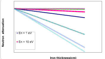
According to these results Iron attenuates high energy neutrons with energy from 100 MeV up to 1 GeV. In the energy region of 100 MeV, 50 cm of Iron are sufficient to decrease the neutron fluence of the above energy interval by 98%. Less than 50 cm are necessary to reduce the neutron fluence with energy from 1 MeV up to 10 MeV by the same factor. The same thickness of Iron can decrease the thermal epithermal neutron fluence by a factor of 77%. This result is mainly attributed to the so-called Iron window at neutron energies around 29 keV and 150 keV (Figure 2). Therefore, an addition of another shielding material is necessary in order to reduce the neutron number in the energy area of 24 keV up to 150 keV.

Figure 2. Neutron attenuation in Iron.
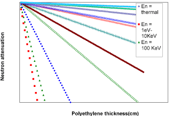
A shielding material which reduces a large amount of neutrons with a mean energy of around 100 keV is the polyethylene, as shown in the (Figure 3). As it is shown only 6 cm of polyethylene is enough to decrease about 99% the number of these neutrons, while polyethylene attenuates a large percentage of neutrons of higher energy. For example, 6 cm of polyethylene cut 76% of 1 MeV neutrons. From figure 3 one can be concluded that as the neutron energy increases the slope of the attenuation curve decreases. Therefore, the thickness of polyethylene should be increased, in order to reduce the number of higher energy neutrons. As an example, if the polyethylene thickness becomes 50 cm, the percentage of neutrons with energy close to 1 MeV will be reduced by about 99%, even greater than the corresponding neutron reduction rate of the same energy from Iron of the same thickness. However, the basic difference between the two shielding materials is the way that neutrons interact with these materials. Neutrons interact with polyethylene mainly through elastic scattering with hydrogen atoms, as opposed to Iron where they interact via non-elastic reactions. Iron has the property of absorbing neutrons, while polyethylene has the ability to shift the spectrum to lower energies. If, therefore, the polyethylene thickness is increased in order to reduce the number of high energy neutrons, a simultaneous increase in the number of thermal neutrons will occur. Because of this built up effect the slope of the thermal neutron attenuation curve decreases.

Figure 3. Neutron attenuation in polyethylene.
In case that two or more shielding materials are used, the order of material arrangement plays a very important role, [3,4]. The heavier material is placed inside, having the greatest chance of interacting with high-energy neutrons and then the lighter materials (Table 2).
Table 2. Combination of different shielding materials.
Shielding Material |
|
Iron
(Fe) |
Polyethylene Borated (ΒPΕ) 5% |
FE +
BPE |
BPE + Fe |
Density |
(gr/cm3) |
7.86 |
0.96 |
4.41 |
4.41 |
Neutrons |
λ (gr/cm2) |
278 |
13 |
42 |
94 |
| |
λ (cm) |
35 |
13.5 |
9.5 |
21 |
| |
E (MeV) |
0.2 |
7.5 |
7.5 |
0.7 |
Photons |
λ (gr/cm2) |
482 |
33 |
98 |
51 |
| |
λ (cm) |
61 |
34 |
22 |
12 |
| |
E (MeV) |
2 |
0.9 |
0.4 |
1.5 |
Considered the lethargy of neutrons and their mean free path, the neutron spectrum behind a shielding can be estimated using Eq. 1 [17]. In order to calculate the neutron spectrum behind a shielding material the neutron spectrum produced by the spallation sources was taken from the calculations made using
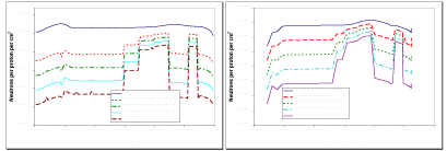
DCM/DEM [20] and MCNPX codes[21]. In calculations, the statistical errors ranged between 3 and 6%. Shielding materials, such as Iron, polyethylene, and paraffin were studied, and the results are summarized in figures 4.

Figure 4a. Calculated neutron spectrum produced by “Gamma-2” spallation source, behind different thickness of Iron. 4b. Calculated neutron spectrum produced by “E+T” spallation source, behind different thickness of Iron.
By integrating the neutron fluence the total neutron ambient dose equivalent was found, considering the dose equivalent factor H*(10) [15,16], for each neutron energy interval. The total time of the irradiation was used to convert the neutron fluence to dose rate.
Experimental results
In order to plan a shielding design of high energy accelerators calculations have been widely used [1,2]. Comparison of the nuclear data with reaction models have not been sufficiently evaluated for accuracy due to the limited experimental data. For these reasons more, experimental results behind shielding materials are needed, especially for deep penetrating radiations.
In the present experiment SSNTDs were placed above the polyethylene moderator surrounding the “E+T” spallation source and above and inside the paraffin moderator covered the “Gamma-2” source.
According to the calculations based on the relationship 1, 26 cm of polyethylene reduce by 97% the number of neutrons with energies of 0.3-3 MeV. The 1 mm Cd before the polyethylene reduces the number of backscattered thermal-epithermal neutrons produced by polyethylene, while the additional 1 mm Cd behind polyethylene reduces the number of thermal-epithermal neutrons escaping from polyethylene. The data of the present experiment indicate that total reduction of thermal-epithermal neutrons behind the polyethylene moderator corresponds to a transmission factor of ~ 8.3 10-2. The transmission factor is the ratio of the neutron ambient dose equivalent values with shield and without shield. The theoretical calculations predict within a good approximation with the experimental results, (Table 3).
Table 3. Attenuation of spallation neutrons from 26 cm of polyethylene and 1 mm Cd. Lead target irradiated with 1 GeV protons.
| |
TRANSMISSION FACTOR |
|
|
Thermal Epithermal Neutrons |
|
Intermediate Fast Neutrons (0.33) MeV |
|
Calculation |
Experimental |
Calculation |
Experimental |
8.38 10-2 |
(8.6 ± 0.34 )10-2 |
2.56 10-2 |
(2.91 ± 0.79 )10-2 |
The transmission factor of neutrons with energy above 2 MeV, in paraffin, was obtained experimentally by fission measurements of fast neutrons, by 232Th [4]. These measurements were performed to study the effect of paraffin on the spectrum of spallation neutrons emitted from a Pb target. According to these measurements, the rate of reduction of fast neutrons, with energy greater than 2 MeV, in paraffin is greater than the rate of reduction of fast neutrons with energy of 0.3-3 MeV in polyethylene. These results are consistent with the theoretical calculations based on relationship 1, which reveal that only 6 cm of paraffin is enough to reduce the number of fast neutrons by 74% (Table 4). The results of the theoretical calculations for two different paraffin thicknesses are in good agreement with the experimental results from measurements made inside the paraffin with fission track detectors [4].
Table 4.Fast Neutron Attenuation by paraffin moderator.
| |
TRANSMISSION FACTOR |
|
|
Paraffin, 3 cm |
|
Paraffin, 6 cm |
|
Calculation |
Experimental |
Calculation |
Experimental |
0.49 |
0.51 ± 0.083 |
0.23 |
0.26 ± 0.052 |
High levels of radiation are generated by a spallation source; therefore, a construction of an appropriate shielding, to surround the source, is necessary for radiation protection purposes. The main objective of the present study was to obtain the neutron ambient dose equivalent produced by two different spallation sources, behind paraffin and polyethylene moderators, by a calculation based on phenomenological aspects and experiment. The materials studied as possible shielding materials were Iron, polyethylene and paraffin. According to these calculations, in order to reduce the neutron ambient dose equivalent to a level of 1 μSv/h, a combination of shielding materials give the best result.
Another important parameter for a shielding design is the order of the materials used relative to the spallation neutron fluence. The heavier material must be placed in front of the incoming high energy neutrons to reduce the dose rate produced by them and then the lighter materials.
The agreement of phenomenological calculations with experimental results demonstrates that calculations based on Moyer Model can be applied to calculate the neutron ambient dose equivalent behind a shielding material and therefore to select an appropriate shielding to surround a spallation source. In addition, this method is practically easier and faster for the calculations of the ambient dose equivalent, even for massive shield materials. The calculated time is independent to the thickness of the shielding material in contrast to the Monte Carlo calculation in which the calculated time is totally depended to the geometry and the thickness of the shielding.
- Bauer GS (2001) Physics and technology of spallation neutron sources. Nucl Instum Meth Phys Res A 463: 505-543.
- Moyer BJ (1961) Evaluation of shielding required for Improved Betaron. Lawrence Berkeley Laboratory report UCRL-9769.
- Fragopoulou M, Stoulos S, Manolopoulou M, Krivopustov M, Zamani M (2008) Dose measurements around spallation neutron sources. Radiat Prot Dosim 132: 277-282. [Crossref]
- Stoulos S, Fragopoulou M, Manolopoulou M, Krivopustov M, Sosnin A, et al. (2004) Neutron measurements by passive methods in the Dubna transmutation assemblies. Nucl Instrum Methods Phys 519: 651-658.
- Krivopustov MI, Chultem D, Adam J et al. (2003) First experiments with a large Uranium Blanket within the installation “Energy plus transmutation” exposed to 1.5 GeV protons. Kerntechink 68: 48-55.
- Adam J, Balabekyan A, Bradnova V, Brandt R, Golovatiouk VM, et al. (2006) Transmutation studies with GAMMA-2 setup using relativistic proton beams of the JINR Nuclotron. Nucl Instrum Methods Phys Res A 562: 741-742.
- Fragopoulou M, Manolopoulou M, Stoulos S, Brandt R, Westmeier W et al. (2006) Spatial distribution of moderated neutrons along a Pb target irradiated by high energy protons. Nucl Instrum Methods Phys Res A 560: 571-576.
- Zamani M, Sampsonidis D, Savvidis E (1996) An individual neutron dosimeter with (n, α) and (n, p) converters. Radiat Measurements. 26: 87-92.
- Van Dijk JWE, Bordy JM, Vanhavere F, Wernli C, Zamani-Valasiadou M, et. al (2001) A review of the properties of the dosimetric systems and the quality assurance programmes of 48 dosimetric services in the European union and Switzerland. Radiat Prot Dosim 96 151-157.
- Sullivan AH (1992) Guide to Radiation and Radioactivity Levels near High Energy Particle Accelerators. Nuclear Technology Publishing, England.
- ICRP (1991) 1990 Recommendations of the International Commission on Radiological Protection. ICRP Publication 60. Ann ICRP 21.
- ICRP (1994) Dose Coefficients for Intakes of Radionuclides by Workers. ICRP Publication 68. Ann ICRP 24.
- ICRP (1997) General Principles for the Radiation Protection of Workers. ICRP Publication 75. Ann ICRP 27.
- ICRP (2007) The 2007 Recommendations of the International Commission on Radiological Protection. ICRP Publication 103. Ann ICRP 37.
- Shin K, Ishii Y (1992) Build-up factor for medium energy neutrons up to 400 MeV. Radiat Prot Dosim 40: 185-194.
- ICRU Report 57 (1998) Conversion coefficients for use in Radiological Protection against External Radiation.
- Fragopoulou M, Zamani M (2013) Phenomenological calculations of shielding spallation neutron sources. Nucl Instrum Methods Phys Res A 714: 24-30.
- Sasaki M, Nakao N, Nunomiya T, Nakamura T, Fukumura A, et al. (2002) Measurements of high energy neutrons penetrated through Iron shields using Self-Tof, NE213 and activation detectors. Nucl Instum Methods Phys Res B 196: 113-124.
- Sosnin A, Polanski A, Petrochenkov SA, Golovatyuk VM, Krivopustov MI, et. al (2002) Influence of different moderator materials on characteristics of neutron fluxes generated under irradiation of lead target with proton beams. Kerntechnik 258: 1-9.
- Hashemi-Nezhad SR, Zhuk I, Kievets M, Krivopustov MI, Sosnin AN, et al. (2008) Determination of natural uranium fission rate in fast spallation and fission neutron field: An experimental and Monte Carlo study. Nucl Instrum Methods Phys Res A 591: 517-529.
- Stevenson G R (2001) Shielding high energy accelerators. Radiat Prot Dosimetry 96: 359-371. [Crossref]


 (1)
(1) (1)
(1)

