Novel g-C3N4/I-TiO2 composite photocatalytic systems, having various wt/wt% of g-C3N4: 0, 30, 40, and 50, were successfully designed and were prepared hydrothermally. The eventually prepared specimens were characterized spectroscopically by Fourier transform infrared (FT-IR), solid-state ultraviolet-visible (UV-Vis) absorbance, X-ray powder diffraction (XRD), and X-ray photoelectron spectroscopy (XPS). Their Brunauer-Emmett-Teller (BET) specific surface areas were estimated by nitrogen physisorption, while their morphology was investigated by scanning electron microscopy (SEM) and transmission electron microscopy (TEM). The photocatalytic activities of g-C3N4/I-TiO2 composites were evaluated by the oxidative degradation of methylene blue (MB) via the irradiation of visible-light having wavelength greater than 420 nm. Tetragonal anatase phase of TiO2 and graphitic carbon nitride (g-C3N4) were detected for the prepared composite catalysts. The composite photocatalyst samples were found to have aggregate semi-spherical particles, as revealed by scanning and transmission electron microscopy (SEM and TEM) investigation.
g-C3N4/I-TiO2 composite photoactive component was incorporated in varying amounts of g-C3N4, and the resulting composites were proved to have improved photoactivity over the composite containing only I-TiO2. Under optimal experimental condition, the 40wt% g-C₃N₄/I-TiO2 composite photocatalyst exhibited the highest photocatalytic activity.
g-C3N4 has the ability to absorb the incident photons, resulting in exciting the electrons between the frontier orbitals. These excited electrons, in turn, move to I-TiO2 via the interfacial border, hindering the recombination of the photo-induced electrons and holes, and thus, improving the performance of the photpcatalyst. This work presented novel g-C3N4/I-TiO2 composite photocatalyst that can be used in waste water remediation. g-C3N4/I-TiO2 composite is a material of particular interest due to its chemical and photo-corrosion stability.
g-C3N4/I-TiO2 composite photocatalyst, hydrothermal method, visible-light photocatalysis, pollutant dye degradation
The photoelectrocatalytic water splitting on titanium dioxide (TiO2) electrode, a discovery of Fujishima and Honda, has given a big area of heterogeneous photocatalysis. This discovery has opened the door for utilizing nanostructured semiconductors in depolluting water through photocatalysis.
TiO2 exists as three different structures or phases: anatase, rutile and brookite [1]. Only anatase and rutile phases with the tetragonal crystal system have appropriate structural advantage for application in photocatalysis. Anatase phase has higher activity in photocatalysis than rutile, but is thermodynamically less stable than rutile [2]. Iodine has also been widely used for activating TiO2 photocatalyst in the visible light region with multiple chemicals states of iodine [3]. g-C3N4 has turned into a hot topic for photocatalysis under visible light irradiation because of its excellent properties, including its visible light band gap (2.7 eV), high thermal and chemical stability, as well as environmental friendly nature. All of these characters of g-C3N4 are responsible for the enhancement of the photocatalytic splitting of water, CO2 photoreduction, photoxidation of organic contaminants in aqueous medium, photocatalytic organic synthesis, and fuel cells by irradiating visible light. The structure of g-C3N4 had a slow recombination and a rapid photoinduced separation in the electron transition. The compositing of TiO2 with g-C3N4 could be an appropriate way to achieve charge separation very efficiently [4].
TiO2 with anatase structure has a wide band gap energy of ~3.3 eV, enabling it to absorb in the UV range of electromagnetic radiation. However, its band gap energy can be tuned for absorbance in the visible range of electromagnetic radiation by doping with nonmetals such as such as (N, S, C, B, P, I, F) [5-7].
Iodine doped titanium dioxide TiO2 absorb strongly the visible light with a reduction in the band gap energy transition [8]. Titania nanoparticles doped with iodine element (I-TiO2), absorbing visible light, can be synthesized hydrothermally. The photocatalytic activity of I-TiO2 samples were evidenced from their ability for the photo-reduction of carbon dioxide with water either under visible light or ultraviolet-visible irradiation. Some researchers attributed the visible light absorbance to the presence of I-O-I and I-O-Ti chemical states on the surface of I-TiO2 [9].
The present work mainly focuses on investigating the synthesis, characterization, and photocatalytic performance, by using the irradiation of visible light, of novel composite photocatalysts composed of g-C3N4, iodine, and TiO2, where both of g-C3N4 and iodine helped to decrease the band gap energy of TiO2 for improving the photocatalytic performance through the improvement of charge separation. We used 3,7-bis(dimethylamino)-phenothiazin-5-ium chloride, commonly known as methylene blue (MB), as a model for organic pollutants. The kinetics of the photodegradation were established.
Materials
Titanium butoxide [Ti(OC4H9)4, Sigma-Aldrich], iodic Acid (HIO3, Aladdin Chemicals), melamine (C3H6N6, Guang Feng Tian Tu Chemical Co. Ltd.), barium sulfate (BaSO4, 99.9%, Aldrich), ethanol (H3CH2OH, Sigma-Aldrich), and methylene blue (C16H18ClN3S, Beijing Chemical Reagents Co.) were obtained commercially and were utilized as received. A Milli-Q water purification system (Millipore, Billerica, MA, USA) was used to obtain ultrapure water (18.2 MΩ.cm).
Physical and Analytical Measurements
All the catalysts samples were characterized spectroscopically by Fourier transform infrared (FTIR) spectrophotometer as potassium bromide (KBr) disks using a Bruker Vertex 70v spectrometer, solid-state UV-visible absorbance as mixture of sample with high purity grade BaSO4 using a Perkin Elmer Lambda 950 UV/VIS/NIR spectrophotometer, powder X-ray diffraction (XRD) using a Bruker D8 Advance diffractometer, and X-ray photoelectron using a JEOL JPS-9200 spectrometer. The morphology of the samples were investigated by using a JEOL JSM-6701F scanning electron microscope (SEM) and a JEOL 2001F transmission electron microscope (TEM). Surface elemental analysis of samples was performed using energy dispersive X-ray spectroscopy (EDS) which is connected to the JEOL JSM-6701F SEM. Specific surface area of samples was measured by nitrogen physisorption at liquid nitrogen temperature (77 K) using Brunauer–Emmett–Teller (BET) method.
Synthesis of g-C3N4
An amount of 5.0 g of melamine was heated at 500°C for four hours with a heating rate of 2°C/min to give a yellow powder at the end [10]. The thermal dissociation of melamine to graphitic carbon nitride is concomitant by the evolution of ammonia gas, as shown in chemical equation (1):
3C3H6N6(c) ⟶ 3g-C3N4(c) + 6NH3(g) (1)
Preparation of g-C3N4/I-TiO2 Composite
A certain amount of g-C3N4 and 0.4 g of HIO3 were ground together. This solid mixture was then added to 100 ml of deionized water (DI) for complete dissolution of iodic acid. The obtained mixture was then transferred into a round bottom flask. An amount of 4.25 ml of Ti(OC4H9)4 was dropped into the mixture with vigorous stirring for 1 hr at ambient temperature. Afterwards, the mixture was transported to a Teflon lined autoclave and was heated at 180°C for 24 hours. After cooling the reaction to room temperature, the mixture was centrifuged at 10,000 rpm for 10.0 minutes at room temperature. The mother liquor was discarded. The left solid was washed with water and then was centrifuged. After decanting the water, the solid was washed with ethanol. After removing ethanol by centrifugation, the solid was dried at 80°C for eight hours in an oven. By varying the amount of g-C3N4, different composites of different weight percentage of g-C3N4 (0, 20, 30, 40, and 50) were prepared. Figure 1 below summarizes the preparation procedure for the composite photocatalyst.
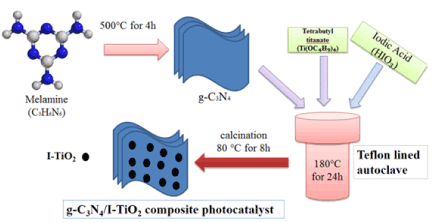
Figure 1. Schematic diagram of the preparation of g-C3N4/I-TiO2 composite photocatalysis.
Photocatalytic Reaction
Methylene blue (MB) is commonly utilized in industry of textile and cosmetics. However, a substantial amount of this dye leaches into water streams, causing serious troubles to human and animal organs and skin; and damages to environment. Therefore, it is mandatory to treat the organic dye-contaminated water before its release.
MB was found to be chemically stable when no photocatalyst was used or light was illuminated, as indicated by the constant concentration of MB in these two cases [10]. The photocatalytic performance of g-C3N4/I-TiO2 composites were determined by measuring the photocatalytic decomposition of MB under visible light illumination at ambient temperature. A xenon lamp, having a power of 500 watt, was used a light source. UV light irradiation was screened by using a colored glass filter allowing light with wavelength of 420 nm or higher to pass to the reactor vessel. A volume of 50.0 ml aqueous solution containing 2 ´ 10⁻5 M of MB, at neutral pH, and 50.0 mg of g-C3N4/I-TiO2 composite powder were added in a beaker made of glass. For establishing the adsorption-desorption equilibrium among the reaction components (MB, H2O, and photocatalyst), the reaction system was stirred with a magnetic bar for 30.0 minutes before exposure to light irradiation.
Figure 2 shows the XRD patterns of TiO2, g-C3N4, I-TiO2, 30wt% g-C3N4/I-TiO2, 40wt%g-C3N4/I-TiO2 and 50wt% g-C3N4/I-TiO2. The identified peaks can be assigned to the tetragonal structure of TiO2 anatase phase (JCPDS No. 21-1272). The very strong diffraction at 25.0o, 37.5o, 47.3o, 54.5o and 67.5o can be assigned to (101), (004), (200), (105), and (204) crystal planes of pure TiO2 with the anatase phase. For pure g-C3N4, the XRD showed two peaks at 13.5 and 27.5 , corresponding to the (100) and (002) crystal planes [11]. The intensity of the (002) crystal plane peak of g-C3N4 increased with increasing the weight percentage amount of g-C3N4 in the composite photocatalyst.
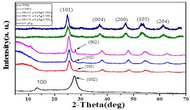
Figure 2. XRD patterns of g-C3N4, TiO2, I-TiO2 and wt%g-C3N4/I-TiO2 composite catalysts.
Figure 3 shows the SEM morphology of pure g-C3N4, I-TiO2 and 40wt%g-C3N4/I-TiO2 composite photocatalysts. In Figure 3a, the pure g-C3N4 has layered structure. Both of I-TiO2 (Figure 2b) and 40wt%g-C3N4/I-TiO2 (Figure 3c and 3d) composite photocatalyst samples have aggregated semi-spherical particles. However, the particles of the 40wt%g-C3N4/I-TiO2 composite photocatalyst is arranged in a layered structure, a feature comes from the g-C3N4. The interfacial interactions between the photocatalyst components would facilitate the movement of internal electrons to the surface of photocatalyst and the separation of photogenerated excitons.
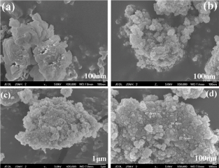
Figure 3. SEM micrograph images of (a) g-C3N4 (b) I- TiO2, (c) and (d) 40wt%g-C3N4/I- TiO2 composite.
TEM and HRTEM images were helpful in revealing the morphology and structure of the as-synthesized samples. Figure 4a shows the TEM image of pure g-C3N4 where the morphology is composed of agglomerated micro-plates. Figure 4b and 4c are the TEM images of 40wt%g-C3N4/I-TiO2 composite where TiO2 can be clearly observed as irregular, agglomerated, crystalline nanoparticles, and g-C3N4 appears as duller and thicker areas of 2-D lamellar, layered structures, indicating the possibility of the presence of a number of stacked layers. a feature of the structure of graphite. Figure 4c is a magnified image of the specimen, where g-C3N4 layers are compacted by TiO2 nanoparticles, indicating a good combination and a close contact among g-C3N4 and I-TiO2, which is required for the formation of heterojunction for a perfect organization to attain better charge separation. Figure 4d shows a HR-TEM image where two different lattice planes of TiO2 in 40wt%g-C3N4/I-TiO2 composite were detected: (001) and (101) [12]. The results of XRD and TEM revealed that anatase TiO2 nano-crystals, having (101) and (001) crystallographic phases on their surfaces, were in direct touch with g-C3N4 in this work.
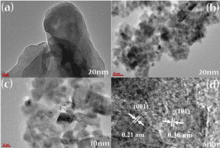
Figure 4. TEM micrograph images of (a) g-C3N4, (b), (c) 40wt%g-C3N4/I-TiO2 and HRTEM micrograph image of (d) 40wt%g-C3N4/I-TiO2 composite.
Figure 5 shows the EDS of 40wt% g-C3N4/I-TiO2 composite photocatalysts. The Ti, O, C, I and N elements were detected in the composite, proving the successful preparation of 40wt% g-C3N4/I-TiO2 composite photocatalysts.
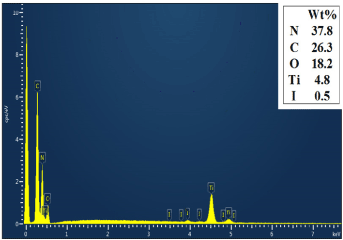
Figure 5. EDS spectrum of 40wt%g-C3N4/I-TiO2.
Figure 6a displays the XPS survey spectrum where peaks for Ti 2p, C 1s, N 1s, O 1s, I 3d3/2 and I 3d5/2 of 40wt%g-C3N4/I-TiO2 composite photocatalyst are detected. Figure 6b shows the binding energies of Ti 2p3/2 and Ti 2p1/2 at 459.5 and 465.1 eV, respectively, which are similar to those of pure TiO2 anatase [13]. Figure 6c displays a peak at 618 eV corresponding to I 3d3/2 and at 629 eV for I 3d5/2. The formation of iodine (I2) in the composite photocatalyst could be assisted by the reduction of iodate ion (IO3-) in the acidic medium to iodide ion (I-) through the abstraction of the two lone pairs of electrons on water oxygen molecules. The eventually produced iodide ion and the iodate comproportionate spontaneously and quickly to iodine (I2), as illustrated in chemical equations (2-5) [14].
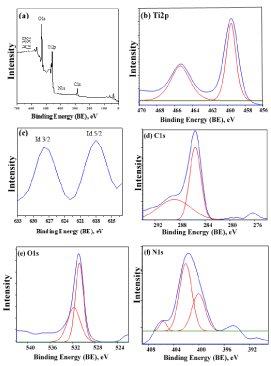
Figure 6. The wide scan (a) and the narrow scan XPS spectra (b) Ti 2p, (c) I 3d3/2-I 3d5/2, (d) C 1s, (e) O 1s and (f) N 1s of the as-prepared 40wt%g-C3N4/I-TiO2.
IO3− + H+ → HIO3 (2)
4HIO3 → 2I2 + 2H2O + 5O2 (3)
4IO3− → 3IO4− + I− (4)
5I− + IO3− + 6H+ → 3I2 + 3H2O (5)
Figure 6d shows the narrow scan of C 1s where two peaks are observed at binding energy of 285. 51 and 288.81 eV. The shaper, more intense peak at 285.51 eV may be ascribed to the bonds between carbons in graphite or amorphous carbon present in the specimen or adsorbed on its surface [15]. The wide, low intensity peak at 288.81 eV refers to g-C3N4 carbon atoms, which are connected to nitrogen atoms [16]. Figure 6e shows the spectrum of O 1s with two peaks centered at 530.70 and 531.78 eV in 40wt%g-C3N4/I-TiO2. These two peaks could be attributed to lattice oxygen and hydroxyl radicals, respectively [17]. The latter peak assigned to hydroxyl radicals indicates the presence of oxygen vacancy and surface hydroxyl, which are active species in semiconductor photocatalyst. These results are in agreement with the FT-IR result where it can be inferred that the interlayer of g-C3N4 has some oxygen attached to carbon (vide infra Figure 7). These active oxygen species may also present on the surface of I-TiO2, as evidenced by FTIR analysis. The high-resolution N 1s XPS spectra in Figure 6f shows three distinct nitrogen environments on the basis of curve deconvolution where the peaks centered at binding energies of 400.60, 402.50, and 404.43 eV. The two peaks at 402.50 and 404.43 eV may be ascribed to nitrogen connected to three carbons and to amine group with a proton, respectively [18]. The peak at 400.60 eV is due to sp2-hybridized N atoms bonded to two carbon atoms (C–N–C) [19]. These observed peaks of N 1s confirm the presence of graphite-like g-C3N4.
The nitrogen adsorption–desorption isotherms are shown in Figure 7a and the pore volume distributions are shown in Figure 7b for I-TiO2 and TiO2. Type IV adsorption-desorption isotherm and H1 type hysteresis loop for I-TiO2 was observed, indicating the mesoporosity of this material with high energy, almost vertical and parallel adsorption and desorption branches in regular even pores without interconnecting channels [15]. Such observation was reported previously due to the functionality of iodic acid (HIO3) as a precursor, pore directing agent, and iodine source [20]. The mesoporosity of I-TiO2 is responsible for the detected high BET specific surface area (SBET) of 223.71 m2g-1. On the other hand, type II adsorption-desorption isotherm and H3 type hysteresis loop for pure TiO2 was detected, indicating non-porosity of this material with high energy of adsorption [21]. This textural feature of pure TiO2 explained its measured low SBET of 9.33 m2g-1. These conclusions regarding the SBET and porosity are supported by the BJH desorption pore volume distribution assessment (Figure 7b) which showed a monomodal distribution for I-TiO2 sample in the mesoporous range with an average pore diameter of 35.440 Å and an average pore volume of 0.255731 cm3/g. On the other hand, the BJH desorption pore volume distribution evaluation of pure TiO2 showed a line parallel to pore diameter axis with values very close to naught on the pore volume axis, confirming the non-porosity nature.
The smallest surface area of 6.1 m2g−1 was noticed for g-C3N4 which was derived from melamine. The synthetic procedure of g-C3N4 has a strong effect on its SBET. When g-C3N4 facet coupled with I-TiO2, the surface area of g-C3N4/I-TiO2 composite photocatalyst decreased with increasing the content of g-C3N4 (Figure 7c) due to the blockage of the mesopores of I-TiO2 by g-C3N4 [22,23]. The SBET of g-C3N4/I-TiO2 is larger than that of the pure g-C3N4 and TiO2, implying interactions between g-C3N4 and TiO2 because of the nanometric size and the well distribution of TiO2 particles within the composite.
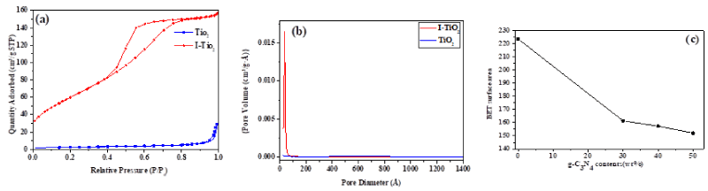
Figure 7. (a) Nitrogen physisorption-adsorption isotherms (b) BJH desorption pore volume distribution for I-TiO2 and pure TiO2, (c) change of SBET with changing the weight percent content of g-C3N4 in the synthesized photocatalyst composites.
Three main IR absorption peaks were detected for TiO2 (Figure 8). The wide band at 3500–3300 cm−1 is due to the O-H stretching vibration of water existing on the surface of the specimen, while the moderately sharp band at 1630 cm−1 is due to the O-H bending vibration [14]. The strong band in the range of 700-500 cm−1 might be attributed to the Ti-O-Ti stretching vibration [24]. On the other hand, three distinctive bands were observed for pure g-C3N4 (Figure 8): the wide band at 3100-3400 cm−1 could be due to the N-H bond stretching vibration, the strong bands in the 1240-1640 cm−1 region with the distinguishing peaks at 1251, 1325, and 1419 cm–1 are owing to the heterocyclic aromatic C-N stretching, the peak at 1571 is due to the C-N stretching [25], and the peak at 806 cm−1 is for breathing mode of tri-azine units [26]. All the distinctive peaks of TiO2 and g-C3N4 were observed in the g-C3N4/I-TiO2 composites, indicating the simultaneous presence of TiO2 and g-C3N4 in the composites [27]. We noticed a small shift in the Ti-O-Ti stretching vibration of the g-C3N4/I-TiO2 composites to lower energy comparing to that of pure TiO2. Such observation could be owing to the interfacial interaction between g-C3N4 and I-TiO2. This strong interaction enables the transportation of the photo-induced charges, in turn, improves the photocatalytic performance [28].
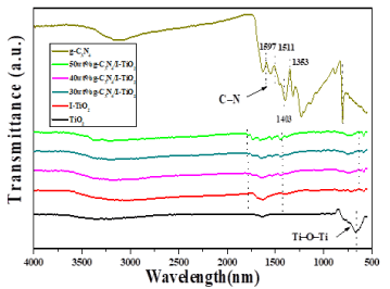
Figure 8. FT-IR spectra of g-C3N4, TiO2, I-TiO2, 30wt% g-C3N4/I-TiO2, 40wt% g- C3N4/I-TiO2, and 50wt% g-C3N4/I-TiO2.
Figure 9 shows the UV–Vis absorbance spectra of the pure TiO2, g-C3N4, I-TiO2 and 40wt% g-C3N4/I-TiO2. g-C3N4 has better absorbance in the visible range than TiO2. Incorporation of iodine into TiO2 enhanced the absorbance in the visible region and exceeded the absorbance of g-C3N4 in the range of 500-700 nm of visible region. The 40wt% g-C3N4/I-TiO2 composite has the best absorbance in the visible light range among all the samples. All samples, except pure TiO2, demonstrate distinctive absorbance of semiconductor in the blue region of the visible light and absorbance related to graphitic carbon nitride.
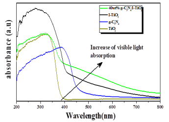
Figure 9. UV–Vis absorbance spectra of TiO2, g-C3N4, I-TiO2, and 40wt% g-C3N4/I-TiO2.
Figure 10 clearly shows the decrease of the characteristic absorbance band, at 664 nm, of methylene blue MB during its photodecomposition over 40wt% g-C3N4/I-TiO2 composite under visible-light irradiation in 100 minutes. To compare the photocatalytic performance of g-C3N4, I-TiO2, g-C3N4/I-TiO2 composites, we first examined the photocatalytic degradation of MB under visible-light irradiation as shown in Figure 11. The change in the concentration of methylene blue MB under visible-light irradiation process showed that the g-C3N4 was superior photocatalyst than I-TiO2 in the first 60 minutes of the reaction, but after that both of them had almost similar visible light photocatalytic activity through indirect dye photosensitization degradation process [29]. After 100 minutes, g-C3N4 was able to degrade 70% of MB, while I-TiO2 degraded 67% of MB.
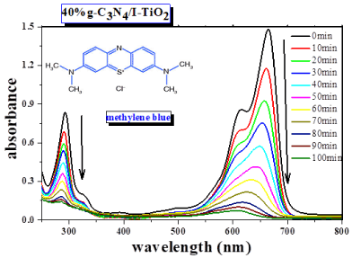
Figure 10. Absorbance spectra of MB at different times after visible light irradiation in the presence of 40wt% g-C3N4/I-TiO2 composite.
The 40wt% g-C3N4/I-TiO2 composite exhibited the highest photodegradation rate of MB under visible light where the final removal% was 99% at 100 minutes of reaction. This priority of 40wt% g-C3N4/I-TiO2 composite in photodegrading MB might be attributed to the highly photon absorbance of the composite photocatalyst in the visible light region (Figure 9). I addition, MB is a kind of photosensitive dye which is beneficial for the degradation process.
Figure 11 shows that the optical absorption intensity of the composite photocatalysts was enhanced with increasing weight percentage of g-C3N4 from 30 to 40. This improvement in photocatalytic activity from 79.5% over 30wt% g-C3N4/I-TiO2 to 99% over 40wt% g-C3N4/I-TiO2 could be owing to the enhancement of the transfer of electrons and holes at the interfaces of photocatalysts, especially the coupling between I-TiO2 (001) facets and g-C3N4 (002) facets, which in turn shifts the band edge potential position of g-C3N4 and of g-C3N4/I-TiO2 composite, and hence, affects the efficiency of generating and separating the electron-hole pairs. However, further increase of g-C3N4 content to 50 wt.% lowered the photocatalytic activity of the composite to 63.5% due to the easiness of the recombination of several photogenerated charges on the surface of g-C3N4.
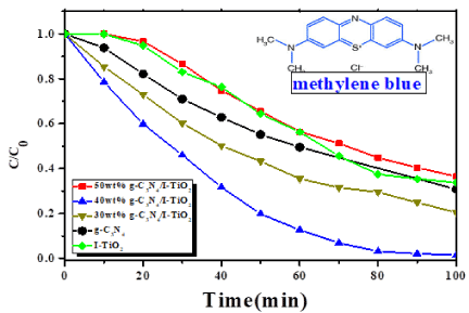
Figure 11. Degradation of MB under visible-light irradiation over different photocatalysts.
To study the reaction kinetic, the obtained data were fitted by a first-order kinetic model, as shown in the equation (6) below:
Where kapp is the apparent pseudo-first-order rate constant, C0 is the original methylene blue concentration, and C is methylene blue equilibrium concentration in aqueous solution at time t.
The photodegradation kinetics of MB over the various g-C3N4/I-TiO2 composite photocatalysts under visible light is plotted in Figure 12. The kapp valued for the photodegradation of MB are 1.11, 0.48, 3.53, 0.86, 4.09 min−1 over g-C3N4, I-TiO₂, 30wt%g-C3N4/I-TiO2, 50wt%g-C3N4/I-TiO2 and 40wt% g-C3N4/I-TiO2, respectively.
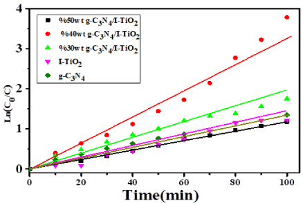
Figure 12. The apparent rate constants under visible light for the degradation of MB over different catalysts.
To explore the photodecomposition mechanism, the band edge potential position of the g-C3N4 and g-C3N4/I-TiO2 composite were calculated. The valence band (VB) potential of a semiconducting material is determined theoretically at the point of zero charge by Equation (7), as follows:
EVB = X − Ec + 0.5Eg (7)
Where EVB is the edge potential of the VB, X is the semiconductor geometric mean electronegativity of the component atoms, Ec is the energy of free electrons on the basis of the hydrogen scale (about 4.5 eV), and Eg is the semiconductor band gap energy. Moreover, the conduction band (CB) edge potential (ECB) can be obtained by ECB = EVB − Eg. The Eg of g-C3N4 and I-TiO2 were estimated to be 2.77 and 3.10 eV, respectively, and the X values for the g-C3N4 and TiO2 are 4.72 and 5.81 eV, respectively. On this basis, the conduction band and valence band edge potentials of g-C3N4 were estimated to be −1.16 and +1.60 eV, respectively. The conduction band and valence band edge potentials of I-TiO2 were assessed to be −0.35 and +2.97 eV, respectively. The less negative value of the conduction band edge potential of I-TiO2 (−0.35 eV) than that of g-C3N4 implies that the photogenerated electrons on g-C3N4 surfaces would moves to I-TiO2 via the well-developed interface. On the other hand, the photogenerated holes would gather in g-C3N4 because the valence band edge potential of g-C3N4 is less positive than that of I-TiO2. Therefore, the oxidation of MB to H2O, CO2, and other molecules takes place on the surface of g-C3N4. On this basis, we depict schematically the probable photodecomposition mechanism of MB overg-C3N4/I-TiO2 composite, as shown in Figure 13.
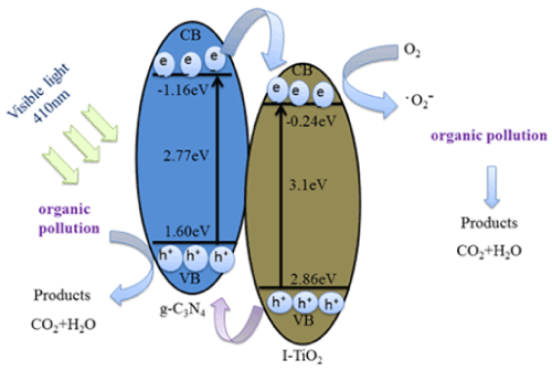
Figure 13. Suggested photocatalytic mechanism of g-C3N4/I-TiO2 composite under visible light.
When g-C3N4 absorbs the incident visible light photons, electrons are excited from its highest occupied molecular orbital (HOMO) to its lowest unoccupied molecular orbital (LUMO). These electrons in the g-C3N4 LUMO might be transported to the LUMO of I-TiO2 at their interfacial interaction. This transfer is responsible for inhibiting the recombination of photo-produced charges and, in turn, considerably improves the photocatalytic activity [30,31]. Furthermore, the presence of (101) and (001) crystallographic phases on the surface of I-TiO2 may produce a heterojunction surface within single I-TiO2 particles, which is useful for transporting of photogenerated electrons and holes to (101) and (001) crystallographic phases, correspondingly [32].
In This research, we succeeded to develop a novel g-C3N4/I-TiO2 composite photocatalysts, which were synthesized readily using a hydrothermal method. The synthesis method produced nanoparticles of the most suitable size (37-47 nm) with layered structure morphologies. The homogeneity of the I-TiO2 nanoparticle distribution within the g-C3N4 was confirmed by SEM/EDS and TEM techniques, while XRD, FTIR, and UV-Vis spectra confirmed the successful preparation of the composite catalysts. These composites were proved to be very successful in the photodegradation MB dye, as a model of organic pollutant, in the aqueous medium. g-C3N4/I-TiO2 composite photoactive component was incorporated in varying amounts in the g-C3N4, and the resulting composites proved to have improved photoactivity over composites containing I-TiO2 or g-C3N4 only under visible light irradiation, at neutral pH.
The photoactive efficiency of these composites was found to depend on the content of the photoactive component, where 40wt% of g-C3N4 was capable of removing ~99% of MB dye under visible light irradiation after 100 minutes of reaction. The structure engineering of composite photocatalyst is a useful tool for constructing unconventional photocatalyst.
We thank King Abdulaziz City for Science and Technology (KACST) and Beijing University of Chemical Technology (BUCT) for using their instrumental facilities to conduct this work. M. Q. A. gratefully thanks KACST for providing him with a scholarship to do his Master of Science degree at BUCT under project No. 34-995. M. Q. A. also extends his gratitude to Dr. Hamid Al-Megren and Dr. Xiaochun Chen, the coordinating of master program between KACST and BUCT, for their all efforts to attain his degree.
M. Q. A. conducted the laboratory work and write the manuscript while A. A. B. guided, supervised M. Q. A., and edited the manuscript.
- Nolan NT, Seery MK, Pillai SC (2009) Spectroscopic investigation of the anatase-to-rutile transformation of sol− gel-synthesized TiO2 photocatalysts. J Phys Chem C 113: 16151-16157.
- Park JY, Lee CH, Jung KW, Jung DW (2009) Structure related photocatalytic properties of TiO2. Bull Korean Chem Soc 30: 402-404.
- Hoffmann MR, Martin ST, Choi W, Bahnemann DW (1995) Environmental applications of semiconductor photocatalysis. Chem Rev 95: 69-96.
- Long M, Cai W, Wang Z, Liu G (2006) Correlation of electronic structures and crystal structures with photocatalytic properties of undoped, N-doped and I-doped TiO2. Chem Phys Lett 420: 71-76.
- Chowdhury S, Balasubramanian R (2014) Graphene/semiconductor nanocomposites (GSNs) for heterogeneous photocatalytic decolorization of wastewaters contaminated with synthetic dyes: a review. Appl Catal B 160: 307-324.
- Zhao J, Chen C, Ma W (2005) Photocatalytic degradation of organic pollutants under visible light irradiation. Top Catal 35: 269-278.
- Yu JC, Ho W, Yu J, Yip H, Wong PK, et al. (2005) Efficient visible-light-induced photocatalytic disinfection on sulfur-doped nanocrystalline titania. Environ Sci Technol 39: 1175-1179. [Crossref]
- Ihara T, Miyoshi M, Iriyama Y, Matsumoto O, Sugihara S (2003) Visible-light-active titanium oxide photocatalyst realized by an oxygen-deficient structure and by nitrogen doping. Appl Catal B 42: 403-409.
- Zhao Z, Liu Q (2007) Mechanism of higher photocatalytic activity of anatase TiO2 doped with nitrogen under visible-light irradiation from density functional theory calculation. J Phys D Appl Phys 41: 025105.
- Dai K, Lu L, Liang C, Liu Q, Zhu G (2014) Heterojunction of facet coupled g-C3N4/surface-fluorinated TiO2 nanosheets for organic pollutants degradation under visible LED light irradiation. Appl Catal B 156: 331-340.
- Long B, Lin J, Wang X (2014) Thermally-induced desulfurization and conversion of guanidine thiocyanate into graphitic carbon nitride catalysts for hydrogen photosynthesis. J Mater Chem A 2: 2942-2951.
- Zhang P, Li X, Shao C, Liu Y (2015) Hydrothermal synthesis of carbon-rich graphitic carbon nitride nanosheets for photoredox catalysis. J Mater Chem A 3: 3281-3284.
- Yuan B, Chu Z, Li G, Jiang Z, Hu T, Wang Q, Wang C (2014) Water-soluble ribbon-like graphitic carbon nitride (gC3N4): green synthesis, self-assembly and unique optical properties. J Mater Chem C 2: 8212-8215.
- Xu L, Xia J, Wang L, Qian J, Li H, et al. (2014) α‐Fe2O3 Cubes with High Visible‐Light‐Activated Photoelectrochemical Activity towards Glucose: Hydrothermal Synthesis Assisted by a Hydrophobic Ionic Liquid. Chemistry 20: 2244-2253. [Crossref]
- Ge L, Han C, Liu J (2012) In situ synthesis and enhanced visible light photocatalytic activities of novel PANI–gC3N4 composite photocatalysts. J Mater Chem 22: 11843-11850.
- Miranda C, Mansilla H, Yáñez J, Obregón S, Colón G (2013) Improved photocatalytic activity of g-C3N4/TiO2 composites prepared by a simple impregnation method. Photochem Photobiol 253: 16-21.
- Wu G, Nishikawa T, Ohtani B, Chen A (2007) Synthesis and characterization of carbon-doped TiO2 nanostructures with enhanced visible light response. Chem Mater 19: 4530-4507.
- Bian SW, Ma Z, Song WG (2009) Preparation and characterization of carbon nitride nanotubes and their applications as catalyst supporter. J Phys Chem C Nanomater Interfaces 113: 8668-8672.
- Cui Y, Zhang J, Zhang G, Huang J, Liu P, et al. (2011) Synthesis of bulk and nanoporous carbon nitride polymers from ammonium thiocyanate for photocatalytic hydrogen evolution. J Mater Chem 21: 13032-13039.
- Liu G, Chen Z, Dong C, Zhao Y, Li F, et al. (2006) Visible light photocatalyst: iodine-doped mesoporous titania with a bicrystalline framework. J Phys Chem B 110:20823-20828. [Crossref]
- Condon JB (2006) Surface area and porosity determinations by physisorption: measurements and theory. Elsevier.
- Ho W, Jimmy CY, Lee S (2006) Low-temperature hydrothermal synthesis of S-doped TiO2 with visible light photocatalytic activity. J Solid State Chem 179: 1171-1176.
- Bai X, Cao C, Xu X (2010) Formation and characterization of flower-like carbon nitride by pyrolysis of melamine. Mater Sci Engineering: B 175: 95-99.
- Li HJ, Sun BW, Sui L, Qian DJ, Chen M (2015) Preparation of water-dispersible porous gC3N4 with improved photocatalytic activity by chemical oxidation. Phys Chem Chem Phys 17: 3309-3315.
- Zhao Z, Dai Y, Lin J, Wang G (2014) Highly-ordered mesoporous carbon nitride with ultrahigh surface area and pore volume as a superior dehydrogenation catalyst. Chem Mater 26: 3151-3161.
- Zhang M, Xu J, Zong R, Zhu Y (2014) Enhancement of visible light photocatalytic activities via porous structure of g-C3N4. Appl Catal B 147: 229-235.
- Zhao HM, Di CM, Wang L, Chun Y, Xu QH (2015) Synthesis of mesoporous graphitic C3N4 using cross-linked bimodal mesoporous SBA-15 as a hard template. Microporous Mesoporous Mater 208: 98-104.
- Xu J, Wang Y, Zhu Y (2013) Nanoporous graphitic carbon nitride with enhanced photocatalytic performance. Langmuir 29: 10566-10572. [Crossref]
- Ihara T, Miyoshi M, Iriyama Y, Matsumoto O, Sugihara S (2003) Visible-light-active titanium oxide photocatalyst realized by an oxygen-deficient structure and by nitrogen doping. Appl Catal B 42: 403-409.
- Cao S, Low J, Yu J, Jaroniec M (2015) Polymeric photocatalysts based on graphitic carbon nitride. Adv Mater 27: 2150-2176. [Crossref]
- Mills A, Le Hunte S (1997) An overview of semiconductor photocatalysis. J Photochem Photobiol A Chem 108: 1-35.
- Wang Y, Wang X, Antonietti M (2012) Polymeric graphitic carbon nitride as a heterogeneous organocatalyst: from photochemistry to multipurpose catalysis to sustainable chemistry. Angew Chem Int Ed Engl 51: 68-89. [Crossref]