In the temporal analysis of facial movement an objective, quantitative analysis is desirable. This can be achieved with the help of 3D systems, like the proposed mirror setup in Figure 1, which was introduced by Frey et al. [1] in 1994. The main advantage of this mirror setup is that it introduces an inexpensive virtual multi camera system. Depending on the angle α, the face of a patient can be seen in up to five different views (Figure 1). This system was designed to measure the progress in facial palsy patients by analyzing the 3D motion of interest points of in the face (e.g. left and right corner of the mouth). Unfortunately, the motion of these interest points is overlaid by the global motion of the head of the patients.
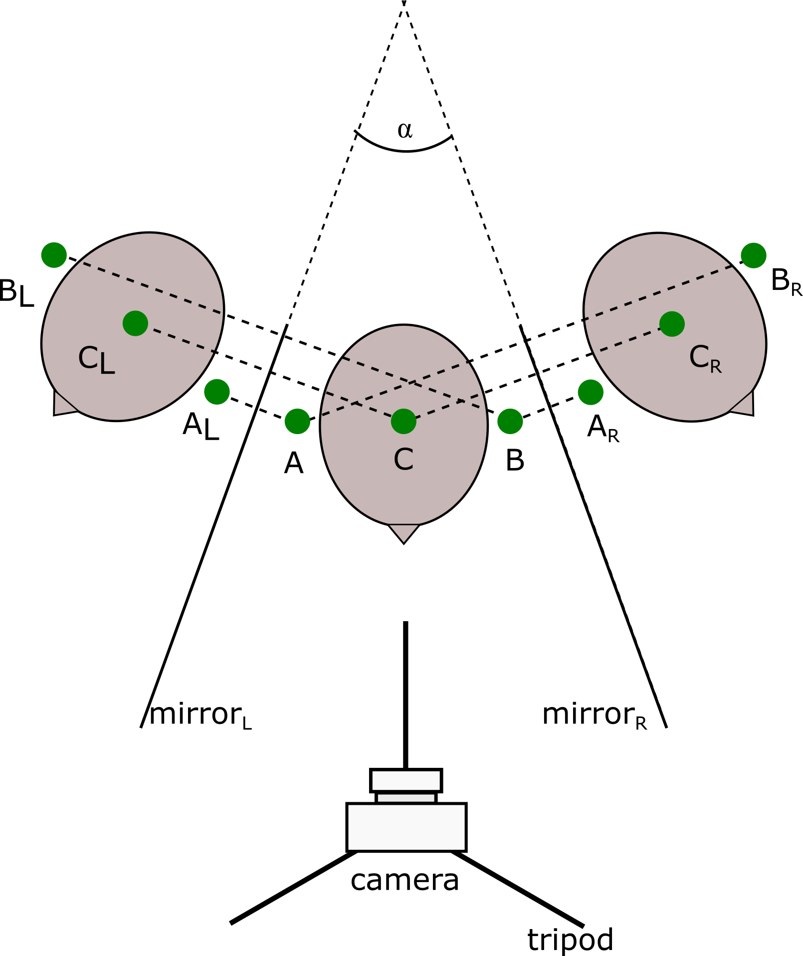
Figure 1. The mirror setup is composed of two mirrors at an arbitrary angle  The subject is positioned inside this setup. The points
  ,
,  and
and  are the static markerpoints in the central view. The points
  ,
,  and
and  are the virtual markerpoints in the left mirror,
  ,
,  and
and  the virtual markerpoints in the right mirror. The camera recording the scene is positioned on a tripod.
Invariance to head motion can be achieved by modelling the its motion using three static markers and introducing an object centered coordinate system. These static markers (Figure 1) are placed above bony structures so that only motion arising from the head influences their position. The introduction of an object centered coordinate system enables to distinguish between motion that arises from the head (global) and motion that arises from the facial movements (local). Based on the methodology introduced by Lin et al. [2], the head motion can be modelled in three dimensional space (Figure 2).
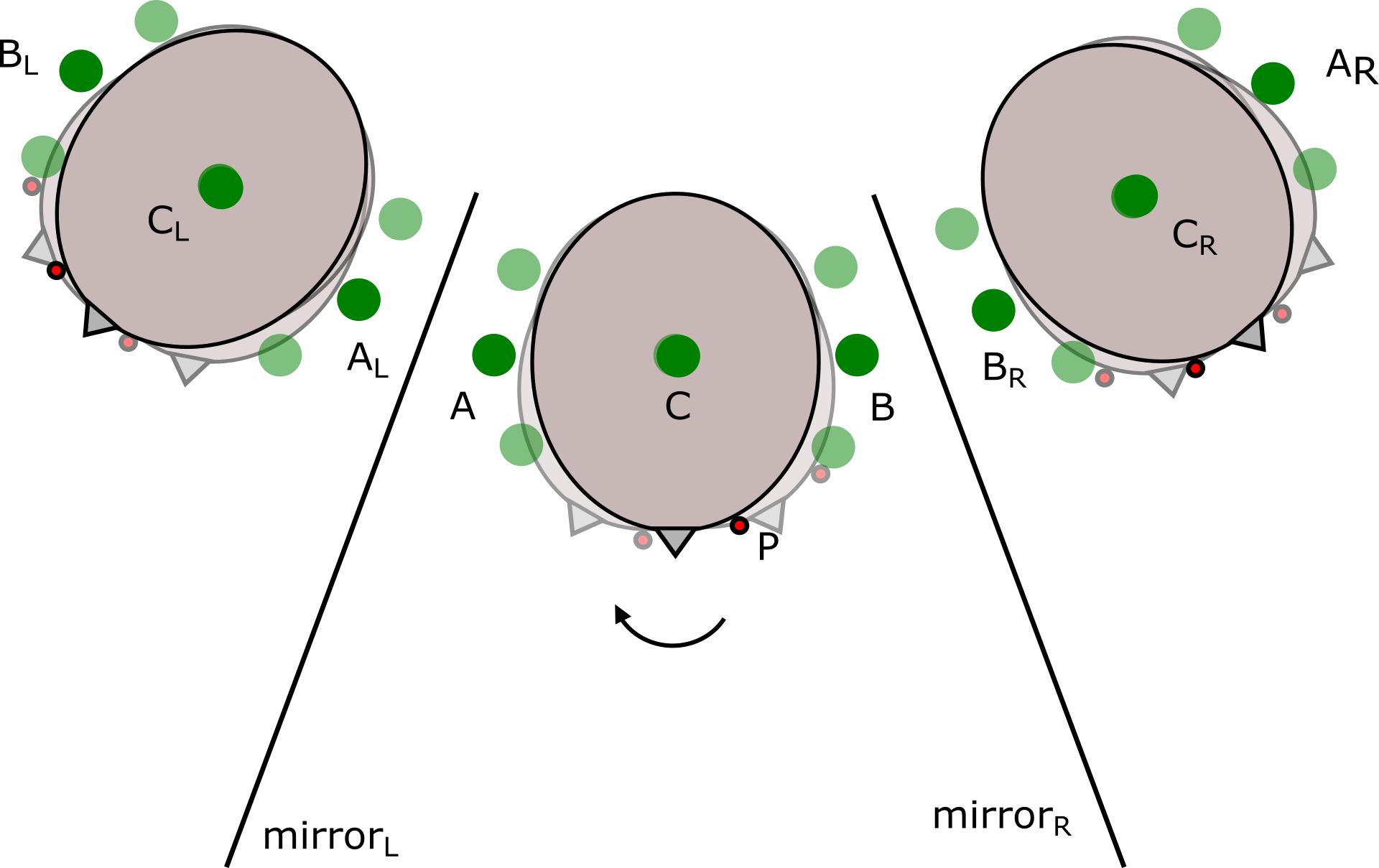
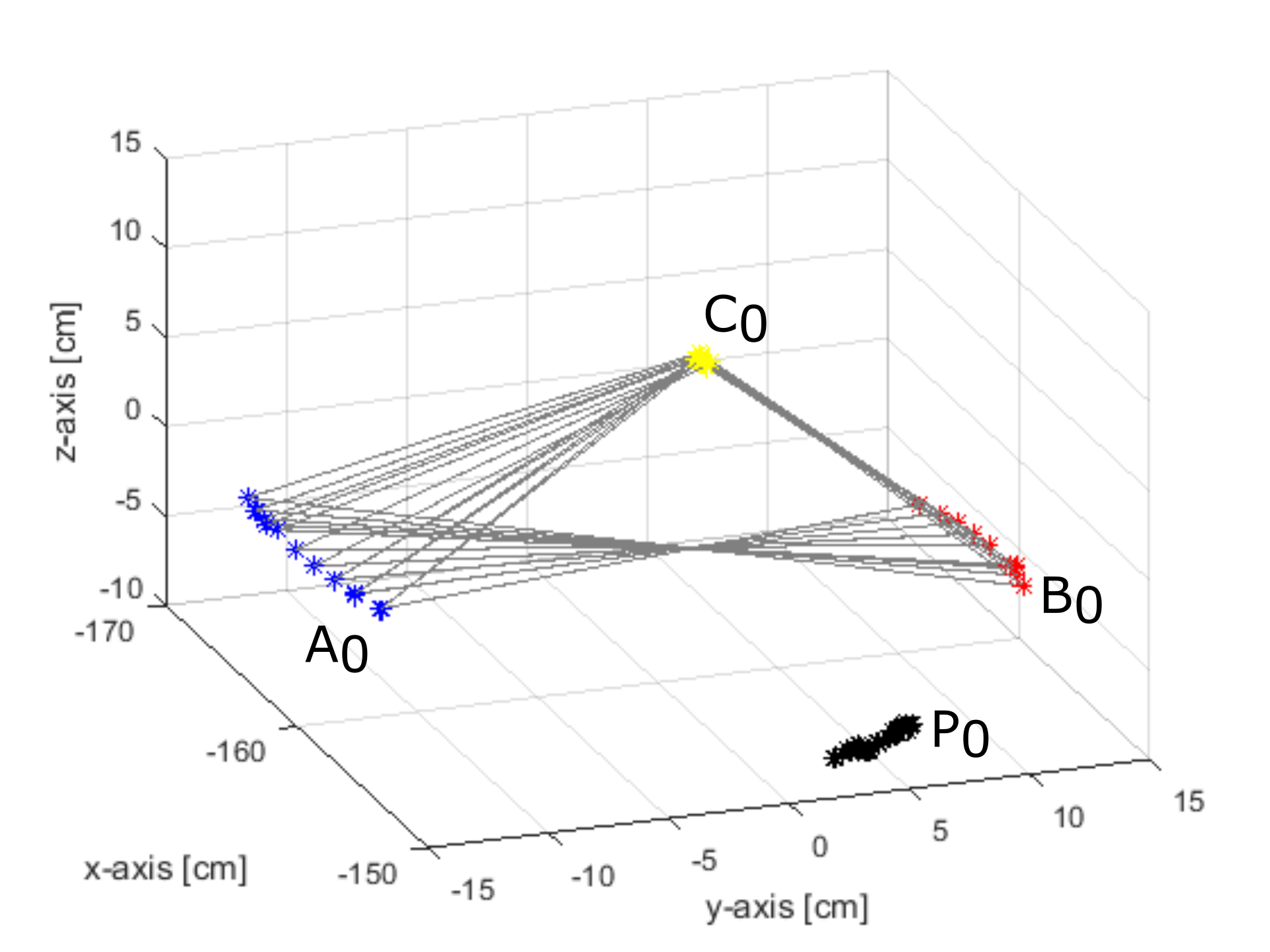
Figure 2. (A): The experimental setup consisted of an artificial head model on a rotary plate, three static markers ( ,
,  and
and  ) and the mirror setup.
  is an interest point, which moves due to the rotation of the head. The artificial head model was manually rotated in 5° steps in counter-clockwise direction. (B) The static markers are used to calculate the 3D head motion. The 3D positions of the markers are represented by
  ,
,  and
and  . The 3D position of the observation point is represented by
  .
.
References
- Frey M, Jenny A, Giovanoli P, Stüssi E (1994) Development of a new documentation system for facial movements as a basis for the international registry for neuromuscular reconstruction in the face. Plast Reconstr Surg 93: 1334-1349. [Crossref]
- Lin I-C, Yeh J-S, Ouhyoung M (2002) Extracting 3D facial animation parameters from multiview video clips. IEEE Computer Graphics and Applications 22: 72-80.