The crude oil production coming from producing fields is forecasted to decline by 67% upto 2020 as a result of 74% increase in world energy consumption, 25% increase in the abandonment of existing producing wells and 65% decline in oil price since 2015 as inevitable cycles of low oil prices continues to be a feature of Oil industry. EK Low-concentration acid IOR (EK LCA-IOR) is one of the emerging EOR technologies which involves the application of the Low-concentration acidizing integrated with electrically enhanced oil recovery (EK-EOR) conducted on Abu Dhabi carbonate core-plugs. This approach is gaining increased popularity due to a number of economic and reservoir-related advantages such as reduction in fluid viscosity, reduced water-cut, increased reservoir permeability, reduced HSE concerns, increased targeting the unswept oil and enhanced depth of penetration. This research focusses on analyzing the effectiveness of the EK LCA-IOR process in Abu Dhabi carbonates, improving the displacement efficiency and capillary number while enhancing depth of penetration.
Carbonate core-plugs, either medium oil-wet or water-wet were flooded with medium crude oil in a specially designed core-flood setup at ambient conditions. After the waterflooding stage, EK LCA-IOR was applied using varying voltage gradients and acid concentrations upto 1.2% HCl injected at the anode and transported by EK to the target producer (cathode). Moreover, the displacement efficiency, permeability enhancement and capillary number change results were analyzed in order to observe the effect on rock-fluid interaction through interfacial tension, capillary number and permeability enhancement.
Several correlations related to acid concentration, displacement efficiency and permeability enhancement have shown that the application of waterflooding on the carbonate cores yields an additional 15-20% oil recovery for water-wet cores while having 25-30% in oil-wet cores. In addition, EK LCA-IOR was shown to enhance the reservoir’s permeability by 42% on average across the water-wet tested core-plugs, but 25% in oil-wet cores. EK LCA-IOR also improves the capillary number by 500% in Water-wet core plugs and 1500% in Oil-wet core plugs, mainly due to a decrease in interfacial tension as a result of reaction between the carboxylic acids contained in the oil and the electrolysis products of brine & HCl along an increased rock surface area causing higher permeability enhancement with higher mobilization of ions along with free water leading to high current density and minimum voltage. This corresponds to doubling the current density on average reduces the pore volume by five times.
Finally, EK LCA-IOR enhances displacement efficiency and capillary number along with an increased depth of penetration while allowing us to save on the OPEX by maintaining decreased power consumption while reducing the acid/water requirement upto 10 times. This study takes one step forward towards the development of EK Low-concentration acid IOR method feasible for Abu Dhabi carbonates.
electrokinetic low-concentration acid IOR, enhancing capillary number, enhancing depth of penetration, stimulation, tight carbonate
Nomenclature
ADNOC: Abu Dhabi National Oil Company, API: American Petroleum Institute, CF: Conventional flooding CAPEX: Capital Expenditure, CO2: Carbon-di-oxide, (CO3)2-: Carbonate, DC: Direct Current, DE: Displacement efficiency, ΔNc: Capillary number change, EK-EOR: Electokinetics Enhanced Oil Recovery, EK LCA-IOR: Electrokinetic Low Concentration Acid Improved Oil Recovery, HCl: Hydrochloric acid, HSE: Health, Safety & Environment, IFT: Interfacial Tension, J: Current Density (A/m2), Kenh: Permeability enhancement (%), OPEX: Operational Expenditure, PI-EKRC: Petroleum Institute – Electrokinetics Research Center, PV: Pore Volume injected, SQ/SEQ: Sequential, SM/SIM: Simultaneous, V/cm: Volt per centimeter (Voltage gradient in Volt/unit), WF: Waterflooding
Enhanced oil recovery status
During the last few decades, there has been a global increase in oil demand by 35% from 2008-2035 due to widespread power generation across the world with an increase in world marketed energy consumption by 53% [1]. There is a fear that the world will be deprived of oil resources due to incapability of the current EOR (Enhanced Oil Recovery) technologies to efficiently enhance oil recovery and globally meet the expected requirements. In order to delay reaching this stage, there is a competition in the area of electrically enhanced oil recovery (EK-EOR) where extensive research has been done [2-9]. It is generally considered that approximately one-third of the hydrocarbon present in existing reservoirs is economically recoverable with commercialized technology [10].
Currently the daily oil production from EOR coming from mature or maturing oil fields and reserves replacement is not keeping pace with the growing energy demand and is still stuck in the mid-10 percent range according to a report [WPC, Oil & Gas, SPE 2014]. This challenge might be due to a large fraction of original-oil-in-place being left behind in the reservoir after the primary and secondary recovery phase in the reservoir as [11]:
1. Uncontacted (unswept) oil (So = 1 – Swi)
2. Partially removed oil (1 – Swi< So > Soi)
3. Residual oil (So = Soi)
To place EOR methods in a proper physical context, it is important to recall that hydrocarbons are trapped in the pores either by an unfavorable viscosity ratio or by capillary forces acting on different scales. For instance, waterflooding or gas flooding (CO2, N2, etc.) with a high oil viscosity leads to an unfavorable mobility ratio between displacing and displaced fluid. A large fraction of the oil is not contacted by the injected fluid and the oil that is contacted is poorly displaced as oil is isolated and trapped as globules by the invasion of water. At flood-out, only trapped isolated oil exists and it is likely to be in the more conductive portions of the pore channels. As the non-wetting phase (water) enters the rock, it first forms tortuous but continuous flow channels through the largest pores. As water injection continues, successively smaller pores are invaded and join to form other continuous channels. When sufficient flow channels form to permit almost unrestricted water flow, oil flow practically ceases, resulting in lower displacement efficiency compared to the water-wet system [12,13]. Capillarity makes it difficult to mobilize oil blobs so that they can be displaced over macroscopic distances. The rock/fluid interactions are responsible for the adhesion of fluids to the porous medium, which can be oil-wet, water-wet, or mixed-wet. In mixed or oil-wet formations, oil is retained in the pores due to the affinity of the oil to the rock.
Several competitive EOR technologies are already been applied in various fields where the target zone varies from moderate to tight reservoir rocks. According to EIA report [14], the crude oil production coming from producing fields is forecasted to decline by 67% upto 2030 due to world marketed energy consumption increase by 74% [15,16]. However, the volume of oil produced from more than 500 EOR field projects [Oil & Gas Journal EOR surveys 1970-2030], doubled from 1980 to 1984 (0.7 MBPD), and then increased by approximately 1000% upto 2015 (10 MBPD), where chemical EOR has shown an increasing trend. Even after the increase in EOR oil production, the petroleum industry is faced with a number of enormous challenges due to declining oil prices [14] and due to reservoir-related parameters, such as low sweep efficiency, wettability, formation damage and implementing costly techniques to enhance the recovery factor of the reservoir. Some of the tertiary EOR technologies already being used in both lab scale and field pilots are divided into as seen in Table – 1:
Table 1. – Limitations of other EOR forms
Thermal EOR |
Chemical EOR |
Gas Injection |
Shallow reservoir to avoid excess heat losses (1000-3000ft) |
High temperature causes degradation of chemicals
|
Source of CO2, N2, H2S and other H-C gases can be limited – availability and transportation issues |
Low % of water sensitive clays is desired and require high oil saturation and pay zone > 15 ft |
Formation water of <20,000 ppm and > 500 ppm is desirable |
Very low viscosity of gases results in poor mobility control and very hard to control MMP. |
Lighter less viscous crude oil may not benefit significantly |
Very high heterogeneity may lead to failure as vertical fractures can cause gravity segregation |
Early breakthrough causes several problems |
Cost per incremental of barrel is high (SOR of 3 to 4, dependent on Pg, has risen to $45-60 on OPEX alone) |
|
CO2 gets dissolved into formation water making it acidic. |
|
High CAPEX for infrastructure |
- Thermal EOR (Steam drive, Steam stimulation)
- Chemical EOR (Polymer, surfactant flooding)
- Miscible EOR (CO2 Flooding, Flue (N2) gas flooding)
Our proposed EK Low-concentration acid IOR (EK LCA-IOR) tertiary technique involves acid injection along with the application of EK which is an emerging technology and will be used on carbonate cores retrieved from Abu Dhabi producing fields. Laboratory experiments are conducted systematically to develop the concept and then results are presented to prove the idea. It will involve performing waterflooding followed by conventional LCA-IOR, complimented by electrokinetics either in a sequential or simultaneous technique.
Authors have worked on a new methodology of low-concentration matrix acidizing with DC (EK driving force). With multiple variations of lab tests, a specific recipe is developed that enables us to implement a number of mechanisms to recover unprecedented amounts of oil with the use of Low-concentration acidizing integrated with Electrokinetics (EK LCA-IOR). This technique uses very low-concentration acid (~95% lower than that applied in the field) with the simultaneous application of EK. The maturity of many fields will require the use of EK LCAIOR based recovery methods to recover residual oil in waterflooded reservoirs. Although conventional acidizing methods were developed mostly for sandstone reservoirs, it has been suggested that fractured carbonate reservoirs have shown great potential for EK LCA-IOR applications. A great additional incentive is that EK LCA-IOR can be engineered as a truly green technology, where there is minimum acid/ water consumption, and no air, water, and formation pollution. The technology can be applied with no depth limitation in-situ rendering it even more attractive in remote operating locations as well as the environmentally challenging ones. Yet, compared to currently incur high costs of conventional electrical oil recovery which depends on joule heating of the formation, EK LCA-IOR may offer a feasible option to augment the flow of these large volumes of crude oil both onshore and offshore.
The above mentioned EK low-concentration acid IOR strategy is applicable to meet the constraints and enhance the production rate by causing an increase in displacement efficiency due to a reduction in interfacial tension and increase in capillary number particularly in oilwet reservoirs. In addition, an important consideration in this largescale study of radial flow experiments is that the acid flux decreases continually as acid moves outward from the wellbore. Moreover, the effective permeability of the matrix is also increased as the process might guide the acid through a precise tortuous path preventing from getting adsorbed too early on the surface that enhances the depth of penetration to penetrate long distances with minimum formation damage and reduces the amount of acid concentration and volume required. Consequently, there is a minimum environmental concern of handling/transporting as moderate to low acid concentration and volume is required and also the flowing oil viscosity, water-cut is reduced with minimum acid consumption and acid corrosion.
Electrokinetics is the application of electric field using electrodes (anode and cathode) where there is a potential difference existing between anode and cathode and the electrokinetic phenomena results from the differential movement of ions across the electrical double layer (EDL). Electrokinetic (EK) application in the oil and gas industry has been rapidly developing over the past 5 years. EK-EOR technology has generated very promising results for sandstone reservoirs in several labs [PI, Lehigh, USC], while showing successful field pilot tests in sandstone reservoirs in North America [1]. To date, the only EKEOR test results on carbonate reservoirs have been conducted at the PI on ADCO retrieved core-plugs and have generated very promising results published worldwide in numerous SPE papers, presentations at the Gordon Research Conference (GRC), as well as published articles in reputable journals and Patents [2-9]. New advances have been contributed to this emerging technology such as EK LCA-IOR and SMART EORTM (EK-assisted Nano and Surfactant Flooding).
Five mechanisms appear to influence EK-EOR including Joule heating, electromigration, electrophoresis, electroosmosis and electrochemically enhanced reactions. All of these mechanisms are collectively called electrokinetics and contribute to oil mobility:
• Joule heating
• Electromigration
• Electrophoresis
• Electro-chemically enhanced reactions
• Electroosmosis
These processes enhance the oil mobility through altering the rock ionic texture, and improve rock permeability which directly increases fluid flow especially in carbonate reservoirs as proven in many previous field and lab studies [2,17]. In addition, carbonate reservoirs have the following complex reservoir characteristics that enable the EK-LCA IOR to act efficiently increasing the displacement efficiency and permeability enhancement:
Heterogeneity of porosity and permeability distributions (high porosity, low permeability).
• Decreasing or increasing salinity (pH) alters the ionic composition through the Electrical Double Layer forces which alters the wettability of the rock surface [18].
• Electric potential gradient imposes new forces on oil/water in pores by altering the wettability and surface charge of reservoir rock by changing the rock composition.
Figure 1 demonstrates a theory of the movement of connate water and injected acid by viscous drag forces at the interface of the mobile layer and free water in carbonate reservoirs containing and devoid of clay content as a result of applied electrokinetics. As a result, cations are accumulated at the cathode and anions at the anode while there is a continuous transfer of H+ and OH- ions into the medium [19-21]. The acid injected at the anode will advance through the soil towards the cathode which is governed by different transport mechanisms including ion migration due to electrical gradients, pore fluid advection due to the prevailing electroosmotic flow, and diffusion due to concentration gradients. This theory requires further investigation by means of tracking the zeta potential across the surface of carbonate rocks with varying mineralogical content and pH as zeta potential is directly related to the stability of a colloidal suspension as a high Zeta potential value gives a stable colloidal system and gives greater repulsion forces [22]. The reservoir rock is mostly dominated by H+ ions creating an overall acidic front mainly due to the following reasons [23,24].
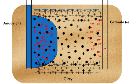
Figure 1. Mechanism to enhance oil recovery during EK LCA-IOR injection [Haroun et al., 2014, Ansari et al., 2014]
• H+ ions have 1.76 times higher mobility than OH- ions
• The H+ ions at anode move towards the cathode with the support of electromigration and electroosmosis reaction whereas the OH- ions progress towards the anode with the support of electromigration only leading to overall neutralization of OHcreating an acidic front.
In our test, the electric field was applied after waterflooding stage was concluded upon recording a 100% water-cut. The trapped residual oil was mobilized by EK mechanisms, increasing the capillary number by virtue of the high transport rate of EK and therefore, transported all the way to the outlet of the core-plug.
EK LCA-IOR Hypothesis
The EK Low-concentration acid IOR proposed hypothesis [25] clearly indicates that Simultaneous EK LCA-IOR has the deepest depth of penetration as it guides the acid through a tortuous path preventing it from getting adsorbed too early on the rock surface, giving the maximum permeability enhancement and oil displacement efficiency with minimum amount and concentration of acid as seen in Table 2 and Figure 2 below.
Table 2. - EK LCA-IOR Hypothesis
|
Conventional LCA-IOR |
Sequential LCA-IOR |
Simultaneous LCA-IOR |
Acid consumption |
Very High |
High |
Low |
Acid concentration |
High |
Moderate |
Low |
Penetration depth |
Low |
Medium |
High |
Penetration depth trend |
∆1 < ∆2 < ∆3 XConv < YSeq < ZSim |
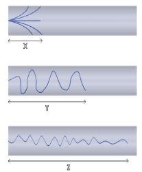
Figure 2. Schematics for EK LCA-IOR Hypothesis
Rock samples retrieved from producing AbuDhabi reservoirs are taken from shallow (basal shale ~ 3500 ft, high porosity with low permeability), moderate (dolomitic limestone ~ 4500 ft), and deep reservoirs (~ 8500 feet) where the porosity in the reservoir ranges between 10 to 25%, and the permeability ranges from as low as 0.1 mD to as high as 16 Darcy. The experiments were conducted on 1.5” core samples in order to simulate and see the effect of EK LCA-IOR on displacement efficiency, permeability enhancement and capillary number at oil-wet and water-wet reservoir conditions.
Core Preparation
Carbonate core-plugs were cleaned and dried in an oven. This was followed by the measurement of their rock properties and saturation with formation water properties (Table 3) for 24 hours at 2500 psi [26,27]. The initial liquid permeability (kabs) of the core was calculated using Darcy’s Law by measuring the differential pressure across the core using a pressure transducer. Then the cores were brought to oil saturation stage at irreducible water saturation condition using medium crude oil (34.50 API) and the relative permeability of oil (kro) and initial oil-in-place (OOIP) was determined after bringing the core to initial reservoir conditions.
Table 3 - Formation water composition to be used at reservoir conditions
Brines / Ions
(kppm) |
Na+ |
Ca2+ |
Mg2+ |
K+ |
SO42- |
HCO3- |
Cl- |
TDS |
FW |
76.68 |
19.12 |
3.35 |
0.08 |
0.11 |
0.06 |
161.81 |
261.21 |
Waterflooding
After saturating the core plugs with crude oil, waterflooding was conducted with formation water at a rate of 0.25 ml/min (equivalent to average reservoir flow rate of 1ft/D for 1.5” cores) under ambient conditions (temperature (30oC) and confined pressure (150 psi) with the application of back pressure across the core. The cores are placed inside a rubber sleeve that fits inside a specially designed steel core holder with insulators at each end to provide insulation for electrokinetics [Figure 3]. The effluent fluid (oil, water or gas) was collected in a burette. Displacement efficiency is used to calculate the efficiency of the oil recovery process as the flow occurs only in 1-D. However, the recovery factor is used to define the oil recovery efficiency in the field when the 3-D radial flow occurs. The displacement efficiency (oil recovery equation – 1), permeability enhancement (found using differential pressure from equation – 2) and capillary number enhancement (found using equation – 3) are the three immense properties that are measured until the pressure stabilizes to quantify the success of the process from equations below:
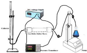
Figure 3. EK LCA-IOR Lab apparatus in PI-EKRC for core flooding at reservoir lab conditions
 (Equation 1)
 (Equation 2)
 (Equation 3)
Where
- ∆Nc = Change in Capillary Number, dimensionless
- ∆v (in cms-1) = (v2 – v1) = (q2 – q1) / A
Fluid flow velocity difference calculated from difference of injection and effluent flow rate divided by cross-sectional area
- ∆µ (in cP (or) 0.01 g/cm-1s-1 ) = (µ2 – µ1)
Difference in viscosity of injection and effluent water using Cannon-Fenske Viscometer
- ∆σ (in dynes/cm (or) g s-2) = (σ 2 – σ 1)
Difference in Interfacial tension of injection and effluent Oil-water using IFT Spinning Drop meter (Figure 4)
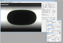
Figure 4. Spinning Drop (IFT) measurement
The following mentions the equipment it contains and their functions:
• Hydrodynamic (Isco) flow pump – Helps to inject, flow and move the fluid through the given core holder setup by providing hydrodynamic flow.
• Core Viton Rubber/Steel core holder - Helps to provide a confinement pressure of 3000 psi and is kept horizontal to eliminate any gravitational effects as the reaction rate is highest when the acid is flowed in the direction of the gravitational force allowing the core-plug to be confined within a rubber sleeve and insulators are applied on either side to eliminate short circuit, through the core cross-sectional area [28].
• Temperature coil and thermometers – Coil is used to apply high temperature for reservoir condition experiments and thermometers measure temperature at two different points at the inlet and outlet.
• Pressure transducer – Helps to record the differential pressure across the core which is important to formulate into core permeability using Darcy’s Law.
• Collector – Is usually a burette or a flask to collect the effluent
• Electrokinetic DC voltage supply: It applies and measures the electrokinetic potential across the given carbonate core in order to measure the current density across the core and quantify other parameters from it.
Conventional LCA-IOR
After the waterflooding stage, conventional low-concentration acidizing was conducted as seen in Figure 5 by injecting acids of different concentrations (0.25% - 1.2%) in a series of experiments axially through the cores at a constant rate of 0.25 ml/min until ultimate waterflood recovery was reached and the final permeability enhancement of the core and its ultimate oil recovery were measured.
Sequential/Simultaneous EK LCA-IOR
This stage can be conducted differently depending upon whether the experiment is conducted sequentially or simultaneously as seen in Figure 5. In this stage, a constant potential gradient (0.5, 1 or 2 V/cm) was applied along with low-concentration acidizing to investigate the effect of Electrokinetics on displacement efficiency, permeability enhancement and capillary number. The DC Voltage was applied with the injector as anode and producer as cathode, until the pressure stabilization and the ultimate displacement efficiency was achieved. A higher voltage gradient applied in the confined core-holder in the lab-scale is required to overcome the current loss due to the electrode reactions occurring at both anode and cathode. However, in the field much lower voltage gradient have been shown to be successful in inducing sufficient EK flow where the common current density range in the field has been observed to fall in the range of 0.01 – 0.1 A/m2 [2-9,29,30]. Additionally, a few experiments in oil-wet reservoir conditions were also performed at constant current density to find an optimum voltage gradient.
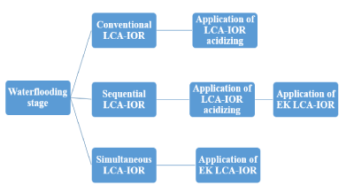
Figure 5. EK Low-concentration acid IOR Approach [Ansari et al., 2014]
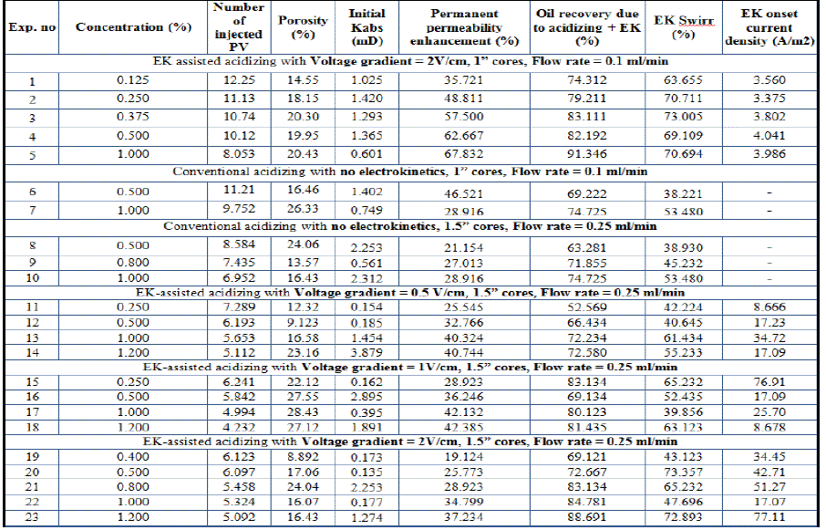
There were 8 core plugs used in our study to investigate the EK LCAIOR approach in 1.5” core plugs at ambient conditions, where the initial petrophysical properties, displacement efficiency and permeability enhancement results as done in previous studies [31-33]. Moreover, their capillary number enhancement including fluid velocity, viscosity and interfacial change is studied in order to investigate the effect of EK Low-concentration acid IOR on capillary number. All the tested core plugs are 1.5” in diameter and 2”-5” long and they are all medium to tight cores with some heterogeneity as the permeabilities range from 0.1 to 4.2 mD and the porosities ranging from 8-22%. The results of the experiments with different voltage gradients at different concentration are plotted as correlations in Figures 6-12, which are discussed in the following sections (Table-4).
Table 4. Results for Low-concentration acid IOR on 1” & 1.5” Ambient water-wet cores
Effect of acid concentration on oil displacement efficiency
Figure 6 indicates that at ambient conditions as the acid concentration increases, the displacement efficiency (recovery factor in 3-D) increases. The main reason for an increase in displacement efficiency is due to an increase in ion (H+) concentration that results in an increase in the effectiveness of electrooosmotic mobile layer (negative in charge) causing an increase in the attraction towards the carbonate rock (positive in charge). Therefore, the diffusion and reaction rate of HCl with carbonates increases clearing more pore throats resulting in an increase in the viscous forces at the interface of mobile layer to contact and displacing more of the by-passed oil not contacted originally. This results in an increase in displacement efficiency with increasing acid concentrations upto a certain optimum concentration (1.2%) beyond which the incremental displacement efficiency decreases with increasing acid concentration. Therefore, the oil displacement efficiency has an exponential relationship with the acid concentration as the acid at higher concentrations above the optimum acid concentration produces increased amount of CaCl2 and CO2 which might hinder the oil production.
Another important finding from Figure 6 is that the maximum displacement efficiency of 88% is achieved with 2 V/cm because a higher voltage gradient provides a higher EK driving force with increased movement of oil droplets across a porous material, capillary tube, membrane having an increased electroosmotic effect [2].
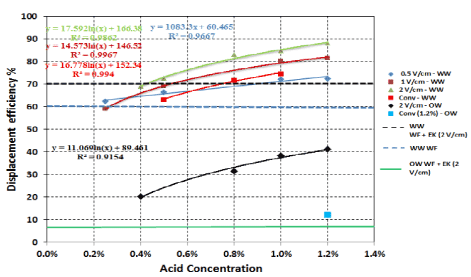
Figure 6. Displacement efficiency as a function of Acid Concentration at different voltage gradients
Effect of acid concentration on oil permeability enhancement
Figure 7 indicates that at ambient conditions there is an exponential relationship between permeability enhancement and acid concentration with diminishing returns at high acid concentrations which might be due to a significant increase in fines production from the stimulation effect that blocks the pore throats which results in reduction of permeability at higher acid concentrations.
It can also be seen from Figure 7 that, 0.5 V/cm has a higher permeability enhancement than 1 V/cm as there is less EK Force and less migration of fines due to a lower voltage gradient and reduced flowing velocity. However, it was also found that the maximum permeability enhancement of 42% is seen with 1 V/cm at 1.2% HCl concentration. This is due to electrophoresis phenomena of EK [2] that results in rigorous migration of clay colloids and micelles or fines emptying the pores potentially increasing the permeability of previously blocked pore throats. In addition to this, 2 V/cm shows a lower permeability enhancement by 23% as compared to 1 V/cm, which might be due to the fact that an increase in voltage gradient increases the EK driving force reducing the contact time between the rock and acid, driving the acid faster lowering the rate at which the Electro-chemically enhanced reactions take place.
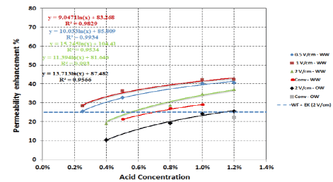
Figure 7. Permeability enhancement as a function of Acid Concentration at different voltage gradients
2021 Copyright OAT. All rights reserv
Displacement efficiency
Figure 8 indicates that Simultaneous EK Low-concentration acid IOR yields the maximum displacement efficiency of 88%, compared to 61% with waterflooding recovery. It is 13% higher by sequential flooding and 30% by conventional flooding. The main reason as proposed in our hypothesis is due to the enhanced depth of penetration provided by Simultaneous approach with a precise targeted transport of acid through the micro pores towards the cathode in the presence of EK leading to increased oil sweep efficiency with negligible acid adsorption at the rock surface. In addition, the application of EK in simultaneous approach has consistently resulted in increasing the net recovery factor by taking the advantage of all the drive mechanisms (Electrosomostic force, hydrodynamic force, microemulsions force) working in conjunction simultaneously in an integrated manner on one big volume of by-passed oil to produce one cumulative net driving force. However, in sequential approach, the application of EK at the end of Low-concentration acid flooding results in lower recovery as all the drive mechanism are segregated in an unstructured way acting on scattered volumes of by-passed oil. Hence, there is increased residence time between the rock and acid leading to increase in acid adsorption at the rock surface which leads to a lower sweep efficiency in sequential approach. Therefore, simultaneous flooding results in targeting more of the present by-passed oil as it has a precise targeted transport of acid through the core.
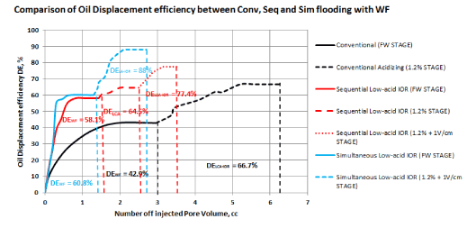
Figure 8. Comparison of Displacement efficiency for Conventional, Sequential and Simultaneous LCA-IOR
Permeability enhancement
Figure 9 indicates that Simultaneous EK Low-concentration acid IOR also yields the maximum permeability enhancement of 53% which is 40% higher by sequential flooding and 55% by conventional flooding. This is due to minimum adsorption that takes place with Simultaneous Low-concentration acid IOR taking the acid through the tortuous path causing the migration of clay particles resulting in enhancing the permeability of previously clogged pore throats. This creates new channels and microfractures through the carbonate rocks. However, in conventional approach it has lower displacement efficiency by 30% and permeability enhancement by 55% as it enhances the natural fracture of tight rocks as the acid takes the least difficult path through the surface leading to a larger consumption of injected acid as proposed in our hypothesis. Conventional LCA-IOR has an additional injected acid consumption of 100-150% as compared to sequential or simultaneous EK LCA-IOR due to the acid getting adsorbed too early in the rock surface leading to acid loss at an early depth of penetration forcing the acid to take the least tortuous path to the rock surface reducing costs spent on CAPEX and OPEX. This is due to early stimulation or displacement efficiency stage reached in simultaneous EK LCA-IOR as all the mechanisms for Electrokinetics and acidizing work in an integrated manner to reach this stage with 50% lower acid consumption than the sequential stage. Additionally, the small amount of acid has reduced adverse environmental impact as it is easily disposable. In terms of reservoir scale this difference could lead to millions of barrels of acid savings and significant reduction of operating costs due to the corrosion and many other flow assurance problems caused in long terms. However, an increased amount of power consumption will be required which can be reduced by optimizing certain parameters during our up-scaling future experiments currently being conducted at the PIEKRC. Therefore, it is more economically feasible and environmentally friendly to use simultaneous or sequential flooding as compared to the conventional approach as seen in our proposed hypothesis [Figure 3].
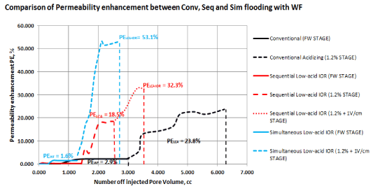
Figure 9. Comparison of Permeability enhancement for Conventional, Sequential and Simultaneous LCA-IOR
DEWF< DE CF< DE EKSQ< DE EKSM
Comparison of Capillary number change between conventional, sequential and simultaneous EK LCA-IOR was evaluated and it was found from Figures 10-11 that simultaneous EK LCA-IOR yields the maximum change in capillary number of 540% which is 39% more than that of sequential LCA-IOR (390%) and 90% more than that of conventional LCA-IOR (282%). The main reason is that Conventional LCA-IOR and Sequential LCA-IOR have increased residence time of the acid in the rock leading to increase in acid adsorption at the rock surface which leads to a lower sweep efficiency. However, Simultaneous EK LCA-IOR accelerates and causes the electrolysis reactions between carboxylic acid in oil and the electrolysis products of brine and HCl generating microemulsions as compared to conventional LCA-IOR that yields the minimum change in capillary number as summarized:
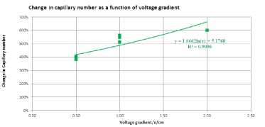
Figure 10. Capillary number increase as a function of Voltage gradient

Figure 11. Summary of change in comparison of change in Capillary number
• The change in capillary number trend for different approaches is as follows:
ΔNc(EEOR) < ΔNc(Conventional LCA-IOR)< ΔNc(Seq EK LCA-IOR) < ΔNc(Sim EK LCA-IOR)
• The capillary number change trend for different voltage gradient is as follows:
ΔNc(0.5 V/cm) < ΔNc(1 V/cm)< ΔNc(2 V/cm)
• The change in capillary number trend for different current densities for Oil-wet rocks is as follows:
ΔNc(4 A/m2) < ΔNc(8 A/m2)< ΔNc(12 A/m2)< ΔNc(16 A/m2)
The success and proof of EK LCA IOR process is demonstrated in Figure 12 where the displacement efficiency and permeability enhancement as a function of increase in capillary number have a strong positive linear correlation (a large value of co-efficient of determination) with the increase in capillary number increasing displacement efficiency and permeability enhancement (Figure 12) as a result of EK LCA IOR method in Abu Dhabi Carbonates. Moreover, to yield a 35% increase in displacement efficiency or permeability enhancement on average, a 400% increase in capillary number is obtained. This proves our concept of EK LCA-IOR increasing displacement efficiency and enhancing permeability having a 400% significant change in capillary number [34,35].
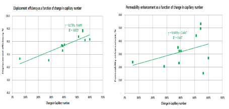
Figure 12. (a) Displacement efficiency and (b) Permeability enhancement as a function of capillary number change
A novel green EK LCA-IOR process was investigated for enhancing displacement efficiency, capillary number and stimulation effect. This potentially increases economic and environmental feasibility. Based on the findings, a comparison was conducted and following conclusions were drawn for Water-wet core-plugs at Reservoir conditions:
• Simultaneous EK LCA-IOR produced higher displacement efficiency and higher permeability enhancement while reducing the acid/water consumption. Therefore, if EK LCA-IOR is applied in a mature reservoir early enough, the efficiency of the EK process would be further enhanced due to a significant reduction in water footprint which is more economically feasible and environmentally friendly
• EK Low-concentration acid IOR produced the trend of voltage gradient as follows:
o Kenh1V/cm > Kenh0.5V/cm > Kenh2V/cm > KenhConv
o DE2V/cm > DE1V/cm > DE0.5V/cm > DEConv
o J2V/cm > J1V/cm > J0.5V/cm
o PVConv > PV2V/cm > PV1V/cm > PV0.5V/cm > PVConv
o ΔNc(2 V/cm) > ΔNc(1 V/cm)> ΔNc(0.5 V/cm)
o ΔNc(16 A/m2) > ΔNc(12 A/m2)> ΔNc(8 A/m2)> ΔNc(4 A/m2)
• An exponential relationship is obtained between acid concentration and permeability enhancement and displacement efficiency with diminishing returns at higher acid concentrations
• Increasing the voltage gradient increases the displacement efficiency and permeability enhancement as the maximum displacement efficiency of 88% and maximum permeability enhancement of 53% achieved with 1 V/cm because a higher voltage gradient provides a higher EK driving force with increased movement of oil droplets across a porous material, capillary tube, membrane having an increased electroosmotic effect and electrophoresis effect
• The effect of voltage gradient in increasing the recovery and permeability enhancement is not very dominant at lower acid concentration which is due to reduced EK force and reduced rate of migration of fines. However, at high concentrations, the effectiveness of electrooosmotic mobile layer portion of the diffuse double layer increases due to an increase in HCl (H+ ion) concentration. This results in an increase in the viscous forces at the interface of the mobile layer and solution allowing the stimulation effect to clear fines that block the pore throats which results in an increase of permeability.
• EK LCA-IOR indicate increase in the capillary number by 200-600% as a result of reaction between the carboxylic acids contained in the oil and the electrolysis products of brine & HCl along an increased rock surface area causing higher permeability enhancement with higher mobilization of ions along with free water leading to high current density and minimum voltage. This corresponds to doubling the current density on average reduces the pore volume by five times.
• Low-concentration acid IOR produces potentially increased economic and environmental feasibility:
o Better formation stimulation results by 29%,
o Better recovery of 15%
o Power consumption was increased by 20%,
o Water/acid consumption was reduced by 70%
Current research phase undergoing at the PI-EKRC is targeted towards using EK LCA-IOR with adjusted parameters such as HCl concentration, Optimizing injection schedule, Injection mechanism and rate.
The authors are thankful to the Petroleum Engineering Department, The Petroleum Institute, Abu Dhabi and ADNOC, for providing the Electrokinetic research center (PI-EKRC) and support needed to conduct this research.
- Wittle JK, Hill DG, Chilingar GV (2008) Direct Current Electrical Enhanced Oil Recovery in Heavy-Oil Reservoirs to Improve Recovery, Reduce Water Cut, and Reduce H2S Production while Increasing API Gravity, Society of Petroleum Engineers, SPE 114012.
- Haroun MR (2009) Ph.D. Dissertation in Petroleum Engineering Feasibility of EEOR in Carbonate Rock Formations, pp. 365
- Haroun MR, Chilingar GV, Pamukcu S, Wittle JK, Belhaj HA, Al Bloushi MN (2009) Optimizing Electroosmotic Flow Potential for Electrically Enhanced Oil Recovery (EK-EOR) in Carbonate Rock Formations of Abu Dhabi Based on Rock Properties and Composition, Society of Petroleum Engineers, IPTC 13812.
- Haroun M, Alhassan S, Ansari A, Al Kindy N, Abou Sayed N, rt al. (2012) Smart Nano-EOR process for Abu Dhabi carbonate reservoirs. SPE 162386 Published in the SPE Abu Dhabi International Petroleum Exhibition and Conference, ADIPEC 2012.
- Haroun M, Wittle JK, Chilingar GV (2012) Patent Publication No. WO/2012/074510 Title of the invention: method for enhanced oil recovery from carbonate reservoirs. applicants: electro-petroleum, INC. (US), Geneva.
- Haroun M, Ansari A, Al Kindy N, Abou Sayed N, Ali B, et al. (2013) Application of Electrokinetics to Achieve Smart EOR in Abu Dhabi Oil-Wet Carbonate Reservoirs Abstract at Electrokinetic Remediation Conference, EREM 2013.
- Haroun M, (2013) Emerging EOR Technologies. OPEC R&D Forum, OPEC Secretariat, Vienna, Austria,
- Ansari A, Haroun MR, Sayed NA, Kindy N, Ali B, et al. (2012) A New Approach Optimizing Mature Waterfloods with Electrokinetics- Assisted Surfactant Flooding in Abu Dhabi Carbonate Reservoirs, SPE 163379, Published in the SPE Kuwait International Petroleum Conference Dhabi International Petroleum Exhibition and Conference, KIPCE 2012.
- Ansari A, Haroun M, Rehman M, Chilingar GV (2014) Increasing Depth of Penetration by Electrokinetic Driven Low-Concentration Acid IOR in Abu Dhabi Tight Carbonate Reservoirs, Society of Petroleum Engineers, SPE 171936, Published in the SPE Abu Dhabi International Petroleum Exhibition and Conference, ADIPEC 2014.
- Hirasaki GJ (1988) Wettability: fundamental and surface forces. SPE/DOE paper 17367
- Tewari DC (2009) Enhanced Oil Recovery techniques, Institute of Reservoir Studies Oil and Natural Gas Corporation Limited, Ahmedabad.
- Seethepalli A, Adibhatla B, Mohanty k (2004) Wettability Alteration during Surfactant Flood in Carbonate Reservoirs, Paper presented in SPE/DOE Symposium on Improved Oil Recovery.
- Sarma HK, Maini BB, Allen G (1992) Effect of Viscous Instability on Unsteady-State Relative Permeability. Revue de L'Institut Francais du Petrole 47: 753-770.
- U.S. Energy Information Administration (EIA), Brent month future prices, 2015.
- Oil and Gas Journal EOR Surveys, EOR surveys 1970-2030, US-Oil-Production-1965-through-2013-Fracking.png?00cfb7
- Taber JJ, Martin FD, Seright RS (1996) EOR Screening Criteria Revisited-Part1: Screening criteria and introduction to enhanced recovery field projects, SPE Reservoir Engineering (August 1997). SPE 35385 presented at the SPE/DOE Improved Oil recovery Symposium, Tulsa, Okhlahoma, 21-24 April, 1996.
- Chilingar GV (1964) Relationship Between Porosity, Permeability, and Grain Size distribution of Sands and Sandstones, Developments in Sediminetology 1: 71-75.
- Alotaibi MB, Nasralla RA, Nasr-El-Din HA (2011) Wettability Studies Using Low-Salinity Water in Sandstone Reservoirs, Society of Petroleum Engineers, SPE149942, Published in the SPE Reservoir Evaluation & Engineering 14
- Eykholt GR (1992) Driving and complicating features of electrokinetic treatment of soils. PhD dissertation, Dept. of Civ. Eng., Univ. of Texas at Austin, TX.
- Pamukcu S, Wittle JK (1992) Electrokinetic removal of selected heavy metals from soil. AIChE Environ.Prog 11: 241-250.
- Acar YB, Alshawabkeh A (1993) Principles of electrokinetic remediation. Environ. Sci. Technol 27: 2638-2647.
- Alkafeef SF, Alforgi MZ (2007) Review of and Outlook for Enhanced Oil Recovery Techniques in Kuwait Oil Reservoirs, IPTC 11234.
- Acar YB, Li H, Gale RJ (1992) Phenol removal from kaolinite by electrokinetics. ASCE J. Geotech. Eng 118: 1837-1852.
- Acar YB, Hamed JT, Alshawabkeh A, Gale RJ (1994) Cd(II) removal from saturated kaolinite by application of electrical current. Géotechnique 44: 239-254.
- Ansari A, Haroun M, Rehman MR, Chilingar GV, (2014) Electrokinetic Driven Low-Concentration Acid Improved Oil Recovery in Abu Dhabi Tight Carbonate Reservoirs, Electrochimica Acta Special Issue (Impact Factor: 4.5). 05/2015, Elseviers 2015, presented at Electrokinetic Remediation Conference, EREM 2014, 07th – 10th September, 2014.
- Byrne M, Patey I (2000) Core Sample Preparation – An Insight in to New Procedures, SCA2004-50
- Sharma MM Effect of Brine Salinity and Crude-oil Properties on Oil Recovery and Residual Saturation, SPEJ 5: 293-300.
- Mumallah NA (1991) Factors influencing the Reaction Rate of Hydrochloric acid and Carbonate Rock. Paper SPE 21036 presented at the SPE International Symposium on Oilfield Chemistry, Anaheim, California 20-22 February.
- Chilingar G, Shin SM, Haroun A, Albannay K, Wittle N (2013) Improving Acidizing Opeations, Journal of Environmental Protection 4: 1-3.
- Wang Y, Hill AD, Schechter RS (1993) The Optimum Injection Rate for Matrix Acidizing of Carbonate Formations, SPE 26578, 657-687
- Ansari A, Haroun M, Rehman M, Sarma H, Chilingar, GV (2015), Enhancing depth of penetration to improve capillary number by Application of EK Low-concentration Acid IOR in Abu Dhabi Carbonate Reservoirs, Society of Petroleum Engineers, SPE 174320, Published in the SPE EUROPEC 2015 Madrid, Spain 2015.
- Ansari A, Haroun M, Rehman M, Chilingar GV, Sarma H (2015) A Novel IOR approach for increasing capillary number by enhancing depth of penetration in Abu Dhabi Carbonate reservoirs, Society of Petroleum Engineers, SPE 177780, Published in the SPE Abu Dhabi International Petroleum Exhibition and Conference, ADIPEC 2015.
- Ansari A, Haroun M, Rehman M, Chilingar GV (2015) Assessing the environomic feasibility of Electrokinetic Low-Concentration Acid IOR in Abu Dhabi Carbonate Reservoirs, Society of Petroleum Engineers, SPE 178124, Published in the SPE Oil and Gas India Conference and Exhibition, OGIC 2015, Mumbai, India.
- Fleureau JM, Dupeyrat M (1988) Influence of an Electric field on the Interfacial Parameters of a Water/Oil/Rock System: Application to Oil Enhanced Recovery. Journal of Colloid and Interface Science 123
- Craft BC, Hawkins M, Terry RE (1990) Applied Petroleum Reservoir Engineering, Second Edition, Prentice Hall PTR, Eaglewood Cliffs NJ 07632.


