Abstract
Background: The research on track and field dynamics is divided into the areas of surface rebound, sprinting with banks, sprint acceleration, and compliant running shoes.
Methods: The dimensionless position (g . x)/V^2 and time (g . t)/V numbers are used for sprint acceleration, and the radius number (g . r)/V^2 is used for speed reduction on circular turns. Equivalent analog circuits are developed, representing the track as an inductor-capacitor L-C resonant circuit, and the runner as an R-L-C oscillator circuit.
Results: Computer results are presented for force, acceleration, velocity, and position during impact. An Impulse Conservation theorem is developed whereby Force × Time=constant.
Conclusion: In addition to a uniform 2% to 3% top speed advantage on optimally compliant surfaces, a tuned track has 11.3% ± 1.21% force reduction for all runners (force reduction factor FR=0.89).
Key words
Resonant tuned track, Force reduction factor FR, Track stiffness, Compliant running shoes, Prosthetic design, Impulse Conservation
Introduction
The subject of running on compliant surfaces is a complex multi-parameter problem in the field of bioengineering. Overall, track and field dynamics involves acceleration, surface rebound response, muscle and tendon mechanics, centripetal forces, bank angle effects, and elastic shoe response. Basic research on human locomotion as it applies to track compliance has significant overlap with other sports, including tennis, basketball, soccer, and from the clinical standpoint, the design of flexible prosthetics.
For the purposes of this report, the subject of track and field dynamics is divided into the categories of acceleration for sprint races, leg-surface rebound phenomenon, running along banks, and design of compliant running shoes. Emphasis throughout is placed on general results, in particular the use of dimensionless variables-the dimensionless position number X*= (g . x)/V 2 and time number T*= (g . t)/V are used to predict sprint acceleration [1]. The radius number R* = (g . r)/V 2 allows predicting all individuals of widely differing top speeds while on banked and circular turns.
Equivalent analog circuits are developed, representing the track surface as an inductor-capacitor L-C resonant circuit, and the runner as an R-L-C damped oscillator circuit. Den Hartog [2] presents a generalized calculation of the optimal “vibration absorber”, determining optimal stiffness, mass, and damping characteristics to minimize force on the system. Liu and Liu [3] and Ozer and Royston [4], extend Den Hartog’s results to cover various new acoustic and multi-component systems. Kim, et al. [5] report remarkable 9.0 g peak forces for humans running barefoot on hard surfaces. Similarly, McMahon and Greene [6] report 3.0 g average forces on hard surfaces. One of the objectives of this report is to quantify the force reduction factor FR on compliant surfaces.
Literature Review
Acceleration phase
Quinn [7] discusses track geometry, the %-percentage of lap length devoted to turns and straightaways, for indoor 200-m and outdoor 400-meter tracks. Greene [1] presents horizontal acceleration characteristics of the sprint runner, based on measurements of peak leg force, finding that the runner’s peak velocity V0 is the only information necessary to determine the position x(t) and velocity v(t) during the acceleration phase on the straightaways. Acceleration factors are most relevant to the sprint events.
Compliant surfaces
One of the best reports on the subject of compliant surfaces is Nigg and Yeadon [8] discussing the calibrated European “impact-leg”, which is dropped onto the surface from a controlled height, measuring realistic g-forces and deflections. A similar device, the Berlin Athlete has been adopted by the I.A.A.F. [9] to calibrate the compliance of competition track surfaces. McMahon [10] and McMahon and Greene [5,11] present measurements of track compliance effects on running speed and reduced initial force spikes. Kerdok, et al. [12], Farley, et al. [13] and Ferris et al. [14] explore experimentally the improved energetics of running on compliant surfaces, finding energetic enhancements in the range 9% to 12%, consistent with results presented here.
Centripetal effects
With flat and banked turns, top speed is attenuated by as much as 50%. Chang and Kram [15] discuss force differentials between the left and right foot when running on flat turns outdoors. Greene [16,17] presents data on flat turns and banks, finding that the runner’s maximum velocity Vo is the only information required to determine the speed-radius eq., a useful simplification. Greene and Monheit [18] present data relevant to track “aspect ratio”, i.e. the %-percentage of lap length devoted to the turns relative to the straightaways, with the unusual result that a perfect circle yields minimal lap time. Ishimura and Sakurai [19] measure that the outside leg plays an important role while running along turns on outdoor tracks.
Compliant Running Shoes
Greene and Coleman [20] present measurements and theory of the vertical deflection characteristics of running shoes. It is determined that running shoe stiffness scales as (1/h), where h is the heel or mid-sole thickness. Frederick [21] and McMahon [10] review compliant running shoes and tracks.
Comparison with other studies
Multi-component mass-spring-dashpot (MKB) systems are also employed by Nigg and Liu [22] to predict the ground reaction forces of non-linear stress-stiffening surfaces. An optimally designed compliant prosthetic leg can reduce ground reaction forces by 9% [23] similar to the 10% to 12% force reduction results presented here. Aruin and Zatsiorsky [24] measure stiffness and damping characteristics for the articulated human ankle joint. Katkat, et al. [25] record muscle performance and surface rebound response for different types of sports surfaces, including asphalt, grass, both natural and synthetic, polyurethane, hard wood, and compacted dirt, indicating significant differences in overall rebound restitution. Kerdok, et al. [12] report a 12% reduction of expended energy on compliant surfaces, a result consistent with the 11.3% reduction of peak foot force, as reported here. It is anticipated that these reductions in peak force are linked to comparable reductions in energy expenditure. Similar energetic enhancements have been reported with athletes using special high-compliance prosthetic lower limbs (Rob Jones, elite marathoner).
Materials and Methods
Mechanics
A 3-component mass-spring-dashpot system is used to describe the interaction of a runner of Mass M1 and leg Stiffness K1, impacting a surface of Mass M2 and Stiffness K2, Figure 1a. The runner’s resonant frequency is given by ω1 = (K1/M1) 1/2, the track resonant frequency is ω2 = (K2/M2 )1/2. The mass of the track is important, because the heavier the surface, the lower the frequency. The mass of the track M2 is usually designed to be less than the mass of the runner M1, as per McMahon and Greene [6]. For the two systems to be in synchrony at resonance, the stiffness of the track K2 must be greater than the stiffness of the runner K1. The stiffness of the runner is a combination of muscles [6] and tendons [26], the order of 8,000 lbf/ft [27,28] for the fastest of the athletic subjects.
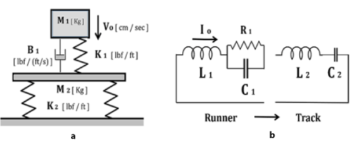
Figure 1. Figure 1a-Runner of MASS M1 impacts track surface of MASS M2 with initial velocity Vo, leg spring stiffness K1, track stiffness K2. Figure 1b-The runner of Mass M1 (equivalent to inductance L1) impinges at Velocity Vo (initial current Io) on Track of Mass M2 (inductance L2) with Track Stiffness K2 (equivalent to Capacitance C2). Force experienced by the runner F(t) is the Inductor voltage VL (t).
Circuits
Equivalently, R-L-C electrical circuits can be developed, Figure 1b, to solve for position as a function of time x(t) and velocity as a function of time v(t) for each system component, with velocity equivalent to current v(t)< --- > I(t), and charge equivalent to position Q(t) < --- > x(t). The damping ratio zeta is given by ζ=0.5 B ω K=0.45-0.55 ~ 50-150 [lbf/(ft/s)] for average runners [6]. Either a numerical iterative solution of Newton’s Law F=m (dv/dt) or from an analog computer observation of circuit behaviour, measuring current as a function of time I(t) and voltage as a function of time V(t), determine the variables of interest, namely foot contact time t1, resonant frequencies ω1 and ω2, and peak impact force Fmax, the primary variable of interest.
Computer calculations
This type of mass-spring-dashpot system is a minimum complexity model, designed to simplify a complicated situation. Basic parameters included are the runner’s Mass, Stiffness, and initial Velocity, allowing calculation of rebound time, maximum force, track and leg positions. The equations can be solved with P-Spice, MATLAB, or Q-Basic (Figures 2a and 2b) or observed on an oscilloscope. The man’s Stiffness K1, equivalent to Capacitance 1/C1, allows calculation of the man’s resonant frequency ω1= [1/(L1 C1)]1/2, compared to the track’s resonant frequency ω2= [1/(L2 C2) ]1/2 . The foot force experienced by the runner F(t) is given by the Inductor voltage VL (t), position x(t) is the Capacitor Voltage VC (t), and velocity v(t) is the Resistor Voltage VR (t). Table 1 below summarizes these equivalent equations.
Table 1. Electrical and Mechanical Equivalents
|
|
Electrical
|
Mechanical
|
Equivalent parameters
|
|
Coulomb
|
Vc=Q/C
|
Hooke
|
F=-Kx
|
Stiffness
|
K ~ 1 / C Capacitance
|
|
Ohm
|
VR=I R
|
Maxwell
|
F=-B (dx/dt)
|
Damping
|
B ~ R Resistance
|
|
Faraday
|
VL=-L (dI/dt)
|
Newton
|
F=m (dv/dt)
|
Mass
|
m ~ L Inductance
|
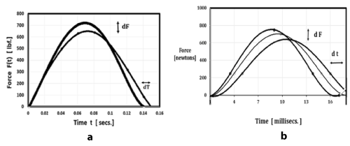
Figure 2. Figure 2a-Force-time results F(t) for runner showing 10% - 12% peak force reduction on soft surface compared with hard, maximum deceleration of 3.6 g reduced to 3.2 g for K1/K2=3:1. Kerdok et al. [12] report similar 12% reduction of expended energy on compliant surfaces. Figure 2b-Experimental force-time data [28-30] for surfaces of various compliances confirms impulse conservation.
Basic equations
The charge on the capacitor is related to its voltage via Coulomb’s Law Vc=Q/C. The voltage across the inductor is proportional to the rate of change of current as per Faraday’s Law V L= - L (dI/dt ). The voltage across the resistor is simply Ohm’s Law V R=I R. These 3 basic equations correspond to Newton’s Law F=m ( dv/dt ), Hooke’s Law for a linear spring F= - K x, and the Maxwell damping resistance F= - B v = -B (dx/dt ), as summarized in Table 1 above. Thus, the Force experienced by the runner as a function of time, the primary variable of interest (Figures 2a and 2b) is equivalent to Voltage V L (t) across the Inductor L1, as shown in Figures1b.
Results
Design, prototypes, construction
Figure 2 shows how added compliance reduces peak foot force for a wide assortment of individuals. This effect is independent of runner mass 11.3% +/- 1.2%, over the range 120 to 240 lbs. In other words, all individuals share equally in terms of the force reduction factor. A total of 10 Tuned Tracks with optimal compliance values were built, including the indoor tracks at Harvard Univ., Madison Square Garden, Yale Univ., the Meadowlands Sports Complex, and the outdoor experimental track at Loughborough Univ.
At the Gordon Track and Field Facility at Harvard Univ., the indoor tuned surface has reduced injuries, and accounted for many world-class performances [10]. Figure 3a shows the Harvard track banked turn inclined at θb=100 degrees for all 6 lanes, in order to improve ankle stability. Note that by banking the turn, the effects of pronating and supinating are reduced to a minimum Figure 3b. Figure 4a is a schematic of ankle geometry showing the effects of pronation. This effect on a flat turn can cause a sprained ankle at high speed. Figure 4b is a banked turn schematic showing idealized runner of mass M, running at velocity V along turn of radius r , with bank angle ϴ, leg stiffness K and damping B, with optimal bank angle given by tan ϴ = [ g . r/V 2 ]- 1. Sub-optimal bank angles (“under-banking”) will cause supination of the right foot and pronation of the left foot. The Radius Number= ( g . r/Vo2 ) allows graphing individuals of different top speed on the same coordinate system [7]. Figure 3b shows a mechanical leg including spring and dashpot elements. In order to stabilize the heel region and simultaneously realize optimal vertical compliance, the Nike SHOX running shoe was developed, Figures 4c and 4d.
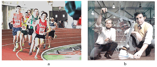
Figure 3. Figure 3a-Harvard track has banked turn at θb=100 degrees, for all 6 lanes. Note that the left and right feet of various runners are “pronating” or “supinating”. Often banking is “under-banked” (θ < θ b) or “over-banked” (θ > θ b). Figure 3b-McMahon and Greene shown working with a spring-dashpot mechanical leg Harvard Univ. 200-meter indoor track.
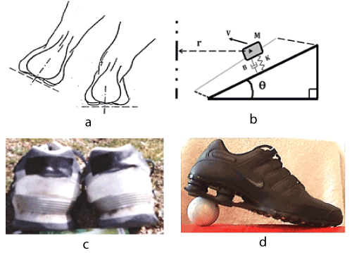
Figure 4. Figure 4a-Pronation and supination effects on an inclined turn compared with a flat turn. This can result in a sprained ankle. Figure 4b-Banked turn schematic, showing idealized runner of mass M, running at velocity V, along turn of radius r, with bank angle ϴ, leg stiffness K and damping B, with optimal bank angle given by tan ϴ = [g. r/V0^2]-1. Figure 4c-after a year of repetitive wear EVA foam in the heel counter region can fatigue, collapsing inward, causing over-pronation, as shown for the right heel. Figure 4d-in order to stabilize the heel region and simultaneously realize optimal vertical compliance, the Nike SHOX running shoe was developed.
Bank angles
An optimally banked turn angle is given by tan ϴ=V 2/( g . r ). As a specific example, with gravity g=32.2 ft/sec2, radius r=30 ft., velocity Vo=22 ft/sec, based on a 4-minute per mile velocity, yields tan ϴ=(222)/(32.2 × 30)=0.5, and thus ϴ ~ 270 degrees. As a practical matter, the innermost lane of the Madison Square Garden track was banked at 220 degrees, slightly “under-banked” for typical competition velocities for the mile. Equivalently, using nominal metric values, with g=9.8 m/sec 2, r=9 m, Vo=7 m/sec, yields tan ϴ= (72)/(9.8 × 9)=.55, thus ϴ ~ 280 degrees, consistent with the result above.
Outdoor construction
Figure 5a is a plan view for outdoor applications, showing that a 440-yard (400 meter) oval track can readily accommodate both a soccer field and a football field, using a 50%-percent aspect ratio for the turns. Figure 4c is a photo of training running shoes, showing that after a year of repetitive wear, some EVA foam types used in the heel counter region can fatigue, causing over-pronation. Delamination is a common problem with outdoor tracks, shown in Figure 5b. After 10 to 15 years exposure to outdoor weather here in the northeast U.S., conventional 0.5”-0.75” inch thick polyurethane surfaces fail as a result of UV exposure, and the constant freeze-thaw cycle during the winter months.
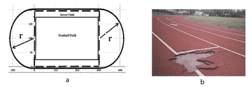
Figure 5. Figure 5a-For outdoor applications, a 440-yard (400-meter) oval track accommodates both a soccer field and a football field, using a 50%-percent aspect ratio, with 50%-percent of the lap length devoted to the straightaway, and 50% percent devoted to the 115-ft radius turns. Figure 5b - after 10 to 15 years outdoors conventional 0.5” polyurethane track surfaces sometimes fail.
Track compliance
In terms of determining optimal track compliance and resulting deflections, a relative minimum in foot contact time is achieved at K2=3 K1 [5,10] using an average runner’s mass of M1=160 lbs. The runner’s stiffness is measured as K2=8,000 lbf/ft [5], so the track stiffness is K1=24,000 lbf/ft. This means that at 3.0 g peak force Fmax=3 × 160=480 lbf, so that track deflection x2=0.25 inch, consistent with measured values. As shown here, 11.3% reduced foot force is realized with a compliant track compared with a hard surface.
Force reduction factor on compliant surfaces
In addition to a speed advantage of 2% to 3% for all runners of widely differing mass, an equally important characteristic is simultaneous reduction of peak foot force by 10% to 12% (force reduction factor FR ~ 0.89). This allows an aggressive long-distance training program while minimizing the likelihood of stress-induced injuries. This also has importance in the design of compliant running shoes (Figures 3c and 3d) and compliant prosthetics. The force reduction of 11.3% +/- 1.2% is shared equally for runners of widely differing mass, over the range of interest M1=120 to 240 lbs.
As shown in the mass-spring system in Figs. 1a and 1b, setting B1=0 and M2=0, solving for the dynamics:
(Equation A-1) Position x(t)=A sin (ω t)
(Equation A-2) Velocity v(t)=A ω cos (ω t)
(Equation A-3) Acceleration a(t)= -A ω^2 sin (ω t)
(Equation A-4) Force F (t)=A m ω^2 sin (ω t)
(Equation A-5) Frequency ω=sqr (K/m), where (1/K)=(1/K1)+(1/K2)
Figures 5a and 5b present calculated and measured force-time results F(t) for runner showing 10% -12% peak force reduction on compliant surfaces compared with hard, with maximum deceleration of 3.6 g reduced to 3.2 g for K1/K2= 3:1. Calculations (App. II) are made in mechanical coordinates using Q-Basic, easily converted to electrical coordinates with the variables from Table 1. Kim, et al. [4] find similar results using a multi-component model with 9 g maximum deceleration during initial foot impact. Kerdok et al. [12] report a similar 12% reduction of expended energy on compliant surfaces. An important practical result, that force reduction effect is the same independent of the mass of the runner, in the athletic range 120 to 240 lbs, <dF> =11.3% +/ 1.21% s.d.
Discussion
Initial work on compliant surfaces originally stems from the 1970’s at the Caulder Racetrack in Florida, with racehorses running on a Tartan Surface several inches thick. Anecdotal reports of speed advantages and force reductions were not thoroughly documented at that time. The area of track and field dynamics is not limited to human athletic performance, it also applies to animal mechanics, and in particular, horse racing and dog racing [31].
Extensions of this work to outdoor 400-meter (440 yard) tracks, football fields, soccer fields, indoor basketball courts, etc., has been quite difficult to achieve as a practical matter. There are many additional difficulties outdoors, not the least of which is the wind load factor. The track surface can react as an airplane wing, whereby wind gusts exert lift forces the order of 2 to 3 lbf/ft 2, tending to dislodge the surface panels. This problem alone can be prohibitive. A temporary solution to this outdoor limitation is to use portable tracks outdoors, storing them for the winter. Another possibility is to use weighted restraints on the peripheral zones.
Additional concerns outdoors are rain, humidity, and the constant freeze-thaw cycle during winter months, Figure 4b. However, in this connection note that residential houses, pleasure boats, and even some aircraft, are made almost entirely of various types of wood. It is a proven technology that by using the proper sealants, epoxy paints, hold-down clamps, tarpaulins, etc., the basic problems of wind-load and dampness can be solved.
A small outdoor compliant track was built at Loughborough University in England, to evaluate the feasibility of constructing a tuned track outdoors, with encouraging results. The lessons learned outdoors were transferred to the Yale Indoor Track [21]. Conceivably, a 3 to 5-year guarantee against the elements is also feasible with an outdoor tuned track, although remarkably, indoor lifetimes for tuned tracks experimentally are ~ 10 times longer, an obvious advantage.
Clinical applications
In terms of medical applications of this research from an orthopaedic perspective, perhaps the most interesting application of this work is the concept of “external tendons” and mechanically powered external “exo-skeletons”, similar to space-suits, designed to augment the reflexive leg stiffness of the individual, for those otherwise impaired. Examples include polio, multiple sclerosis, and prosthetic limb design [32,33]. These techniques fall under the category of active and passive exo-skeletons. The most familiar example of this type of exoskeleton is the elastic racing suit for runners. This work is also directly applicable to the field of “robotics”, particularly for military applications, whereby series and parallel actuators are linked to compliance elements to simulate multi-legged locomotion over difficult terrains (Bostondynamics.com).
Other analog circuit applications include the design of earth-quake proof buildings, whereby seismic “vibration dampers” [34] are installed on the roof-tops of tall buildings, for the purpose of counter-acting in a resonant way the vibrations imposed by an earthquake. A new application is the design of “resonant back-packs” [35] oscillating with the runner’s natural frequency.
Marathon applications
The runner compensates for the slower frequency with a slightly longer step length, in order to maintain speed. Thus, a relatively small change in compliance can produce a large advantage in terms of comfort and speed. In terms of athletic design, the most promising application of force-reduction and speed enhancement is the exceedingly difficult 26.2-mile marathon. While the current record is the order of ~ 2h 3m (~123 minutes, at a 4.7 minute/mile pace), some speculate that a 2-hour marathon is possible. Note that a 2%-3% speed advantage with a well-designed compliant surface, translates to 5-8 seconds saved per mile, so over the course of 26.2 miles this accumulates to saving 2.2 to 3.5 minutes, just enough to break the 2-hour record. In addition, the 10% to 12% force-reduction effect is expected to translate to a savings in expended muscle power [36], since power per stride is <P>= (1/t1) ∫ F(t) × v(t) dt.
Conclusion
The primary result of this compliant surface research is a uniform 2% to 3% enhanced top speed for all runners regardless of their individual parameters. An equally important result is an 11.3% reduction of foot force, an advantage shared equally by all runners.
Declaration of Interest Statement
The author has no proprietary or financial conflicts of interest. This work was supported in part by Harvard Univ., Yale Univ., and a Whitaker Foundation Grant at Johns Hopkins University.
Acknowledgements
Thanks go to Rob Franklin, Howard Schmertz, Bob Giegengack, Charles Blanford, Bill McCurdy, Tony DiNatale at Champion Sports, Floyd Highfill at Tracks West, Don Gordon at En-tout-cas Ltd., Peter Cavanagh, Ned Fredericks at Nike, Peter Manus, David Cuin at Int’l. Athletics and Tom McMahon for many helpful discussions. Special thanks to Charles Blanford and Bob Giegengack at IAAF and IOC for suggesting the original turn radius and bank angle projects, and Steve Atkinson and Bill McCurdy at Harvard University for suggesting the original track compliance studies. Students at Harvard and Johns Hopkins University were most helpful with the experiments and computer work. This work is dedicated to Tom McMahon.
References
- Greene PR (1986) Predicting sprint dynamics from maximum-velocity measurements. Mathematic Biosci 80: 1-18.
- Den Hartog JP (1956) Mechanical Vibrations. Courier Corporation, New York.
- Liu K, Liu J (2005) The damped dynamic vibration absorbers: revisited and new result. J Sound Vibration 284: 1181-1189.
- Ozer MB, Royston TJ (2005) Extending Den Hartog’s vibration absorber technique to multi-degree-of-freedom systems. J Vibration Acoustics 127: 341-350.
- Kim W, Voloshin AS, Johnson SH (1994) Modeling of heel strike transients during running. Hum Move Sci 13: 221-244.
- McMahon TA Greene PR (1979) The influence of track compliance on running. J Biomech 12: 893-904. [Crossref]
- Quinn MD (2009) The effect of track geometry on 200-and 400-m sprint running performance. J Sports Sci 27: 19-25. [Crossref]
- Nigg B, Yeadon MR (1987) Biomechanical aspects of playing surfaces. J Sports Sci 5: 117-145. [Crossref]
- IAAF (2008) IAAF Track and Field Facilities Manual Editorial Board.
- McMahon TA (1984) Muscles, reflexes, and locomotion. Princeton University Press.
- McMahon TA, Greene PR (1978) Fast Running Tracks. Sci Am 239: 148-163.
- Kerdok AE, Biewener AA, McMahon TA, Weyand PG, Herr HM, et al. (2002) Energetics and mechanics of human running on surfaces of different stiffnesses. J Appl Physiol 92: 469-478. [Crossref]
- Farley CT, Glasheen J, McMahon TA (1993) Running Springs: Speed and Animal Size. J Exp Biol 185: 71-86. [Crossref]
- Ferris DP, Louie M, Farley CT (1998) Running in the real world: adjusting leg stiffness for different surfaces. Proc Biol Sci 265: 989-994. [Crossref]
- Greene PR (1987) Sprinting with Banked Turns. J Biomech 20: 667-680. [Crossref]
- Chang YH, Kram R (2007) Limitations to maximum running speed on flat curves. J Exp Biol 210: 971-982. [Crossref]
- Greene PR (1985) Running on Flat Turns: Experiments, Theory, and Applications. ASME J Biomech Eng 107: 96-103. [Crossref]
- Greene PR, Monheit MA (1990) Optimal Geometry for Oval Sprint Tracks. J Biomech 23: 447-452. [Crossref]
- Ishimura K, Sakurai S (2016) Asymmetry in Determinants of Running Speed During Curved Sprinting. J Appl Biomech 32: 394-400. [Crossref]
- Greene PR, Coleman JD (2015) Elastic Spring Constants for Running Shoes. J Comput Sci Syst Biol 8: 215-218.
- Frederick EC (1984) Sport Shoes and Playing Surfaces. Human Kinetics, Champaign Illinois.
- Nigg B, Liu W (1999) The effect of muscle stiffness and damping on simulated impact force peaks during running. J Biomech 32: 849-856. [Crossref]
- Grabowski AM, McGowan CP, McDermott WJ, Beale MT, Kram R, et al. (2010) Running-specific prostheses limit ground-force during sprinting. Biol Lett 6:201-204. [Crossref]
- Aruin AS, Zatsiorsky VM (1984) Biomechanical characteristics of human ankle-joint muscles. Eur J Appl Physiol Occup Physiol 52: 400-406. [Crossref]
- Katkat DY, Demir B, Akar S (2009) Effects of different sport surfaces on muscle performance. Biol Sport 26: 285.
- Greene PR (1985) Constant Strain Increments for Exponential Tendons in the High-Stress Limit. J Biomech Eng 107: 291. [Crossref]
- Benanti M, Andena L, Briatico-Vangosa F, Pavan A (2013) Viscoelastic behaviour of athletics track surfaces in relation to their force reduction. Polymer Testing 32: 52-59.
- Greene PR, McMahon TA (1979) Reflex Stiffness of Man’s Anti-Gravity Muscles During Kneebends while Carrying Extra Weights. J Biomech 12: 881-891. [Crossref]
- Andena L, Briatico-Vangosa F, Cazzoni E, Ciancio A, Mariani S, et al. (2015) Modeling of shock absorption in athletics track surfaces. Sports Eng 18: 1-10.
- Meijer K, Dethmers J, Savelberg HH, Willems, P, WIjers B, et al. (2007) The influence of third generation artificial soccer turf characteristics on ground reaction force during running. ISBS Conference Proceedings Archive 1: 1.
- Usherwood JR, Wilson AM (2005) Biomechanics: no force limit on greyhound sprint speed. Nature 438: 753-754. [Crossref]
- Van den Bogert AJ (2003) Exotendons for assistance of human locomotion. Biomed Eng Online 2: 17. [Crossref]
- Herr H (2009) Exoskeletons and orthoses: classification, design challenges and future directions. J Neuroeng Rehabil 6: 21.
- Chen KC, Wang JH, Huang BS, Liu CC, Huang WG, et al. (2013) Vibrations of the TAIPEI 101 Skyscraper Induced by Typhoon Fanapi in 2010. Terr Atmos Ocean Sci 24: 1.
- Ackerman J, Seipel J (2011) Energetics of bio-inspired legged robot locomotion with elastically suspended loads. IEEE/RSJ Int Conf on Intelligent Robots Syst pp: 203-208.
- Dasika SK, Kinsey ST, Locke BR (2011) Reaction–diffusion constraints in living tissue: Effectiveness factors in skeletal muscle design. Biotechnol Bioeng 108: 104–115. [Crossref]


