Facial trauma in growing patient may cause excessive development of bone or can limit it because of scar tissue, mostly in growing centers such as condyle or alveolar bone. Earlier the trauma is, the more the injury is and it is hard to recognise functional and occlusal changes during growing period. Alveolar bone in children deforms after trauma but doesn’t fracture [1].
If tooth follicle is injured, permanent tooth can be displaced, and it will be a problem its extrusion. Tooth follicle guides tooth extrusion [2].
In 2013, in the orthodontic department of G. D’Annunzio University in Chieti (ITALY), an eleven years old girl refers to have hurt the left part of the superior jaw, falling off bike, when she was five years old. She has noticed that in her mouth there is something strange.
Diagnosis and Treatment
Initial CBCT images (Figure 1)
OPT (Figure 1): all permanent teeth are present but their eruption is delayed – there are some decayed teeth and some deciduous roots fragments – the tooth 3.5 is already erupted (other inferior bicupids and canines are not erupted) – the upper right bicuspids are erupted ( the left ones are not erupted yet) – the tooth 1.3 risks to be impacted, due to its inclination and mesial position – the tooth 2.1 is 90° rotated along its axis – the tooth 2.3 is transposed on the root of the tooth 2.2, which is horizzontally laying near bicuspid roots (Figure 2).
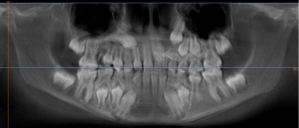
Figure 1. INITIAL OPT
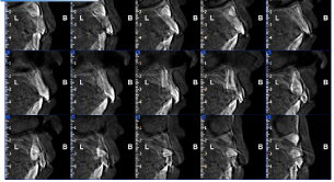
Figure 2. CROSS SECTIONS SHOW 2.1 ROTATED, 2.3 TRANSPOSED ON 2.2 LAYING
Tele RX: Figure 3 and Table 1
Table 1. Initial chefalometric analysis
GoGn- SN |
37° |
32 ± 5 |
ANG. INTERI |
127° |
132 ± 6 |
FMA |
26° |
22-28 M |
ANG. SELLA |
130° |
122 ± 5 |
MM |
25° |
28 ± 6 |
ANG.ARTICO |
135° |
143 ± 6 |
SNA |
81° |
82 ± 2 |
ANG. GONIA
SUP
INF |
131°
56°
75° |
120 ± 5
50 ± 2
70 ± 3 |
SNB |
75° |
80 ± 2 |
+1 A Pog
-1 A Pog |
6mm
1mm |
3,5 ± 2
2 ± 2 |
ANB |
6° |
2 ± 2 |
WITTTS RIC
WITTS REAL |
6mm |
0 ± 2 |
+I Sna-Snp
+I PFH
+I SN |
111°
112°
100° |
113 ± 2 B
113 ± 1 B
103 ± 2 |
A –MC NAM
Pog-MC NA |
3mm
-4mm |
|
IMPA |
96° |
90-96 B |
|
|
|
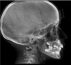
Figure 3. LATERAL CRANIUM RX
Normal facial height – second class skeletal pattern due to retrusive mandible – upper and lower incisors proclined – forward mandibular growing direction, changes toward clockwise rotation, due to upper and lower incisors contact – 3mm overjet - 2mm overbite.
Frontal RX: Inclined occlusal plane – mandibular right deviation (Figure 4)
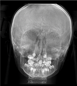
Figure 4. FRONTAL RX
Palatal suture: Open suture (Figure 5)
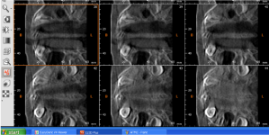
Figure 5. PALATAL SUTURE
Temporo mandibular joint: Retropositioned, curved and flattened condyles (Figure 6)
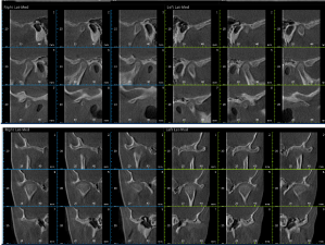
Figure 6. TMJ CROSS SECTIONS
Extraoral photos: (Figure 7)
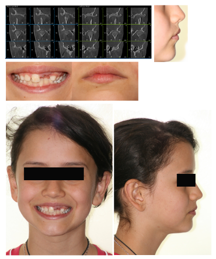
Figure 7. EXTRAORAL PHOTOS
Intraoral photos: Dental upper midline toward left – lower dental midline toward right (during opening mouth it is steel deflected) – inclined occlusal plane – narrow upper dental arch (Figure 8)
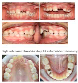
Figure 8. INTRAORAL PHOTOS
AFTER TWO MONTHS: Dental occlusion has been increased to let tooth 2.1 to extrude and so a bracket can be put on it (Figure 9)
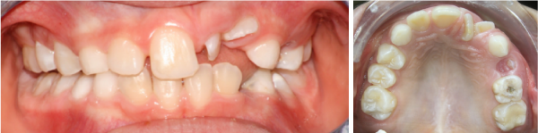
Figure 9. AFTER TWO MONTHS
In the upper arch there is a rapid palatal expander with right buccal extension to stop the tooth 1.1, while rotating the tooth 2.1 (Figure 10)
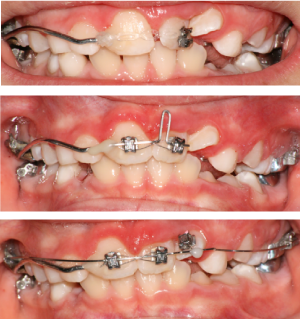
Figure 10. TOOTH 2.1 ROTATION
The rapid palatal expander has been modified to pull down upper canines (Figure 11)
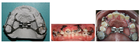
Figure 11. MODIFIED RAPID PALATAL EXPANDER
In 2015 brackets DAMON Q have been positioned in the upper arch, except on the tooth 2.2 and the tooth 2.3 has been exposed to put on it a botton (Figure 12)
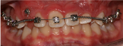
Figure 12. BRACKET DAMON Q
A JIG, made of rectangular stainless-steel wire, has been used to increase space for the tooth 2.3
Then the space has been managed using a coil between teeth 2.1 and 2.6 (Figure 13). The tooth 2.2 has been managed using an overlay wire (the bracket on the tooth 2.2 has been tipped to upright the root toward the midline and the bracket has been placed upside-down to let the root correct its torque when a rectangular wire is placed in the slot) (figure 13 last one)
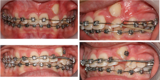
Figure 13. JIG AND COIL FOR SPACE
Then the tooth 2.3 has been managed using an overlay wire too and a lace back (Figure 14)
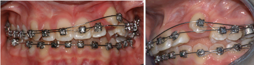
Figure 14. OVERLAY WIRE
Intercuspidation elastics with a direction to correct the second class, have been positioned for almost a month (Figure 15)
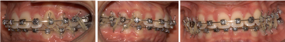
Figure 15. INTERCUSPIDATION ELASTICS
After a year, photos in static and dinamic position, extraoral photos and CBCT images (Figures 16-19) and Table 2
Table 2. Final chefalometric analysis
GoGn- SN |
31° |
32 ± 5 |
ANG. INTERI |
124° |
132 ± 6 |
FMA |
24° |
22-28 M |
ANG. SELLA |
130° |
122 ± 5 |
MM |
21° |
28 ± 6 |
ANG.ARTICO |
130° |
143 ± 6 |
SNA |
83° |
82 ± 2 |
ANG. GONIA
SUP
INF |
132°
56°
76° |
120 ± 5
50 ± 2
70 ± 3 |
SNB |
79° |
80 ± 2 |
+1 A Pog
-1 A Pog |
4mm
1mm |
3,5 ± 2
2 ± 2 |
ANB |
4° |
2 ± 2 |
WITTTS RIC
WITTS REAL |
1mm |
0 ± 2 |
+I Sna-Snp
+I PFH
+I SN |
121°
119°
110° |
113 ± 2 B
113 ± 1 B
103 ± 2 |
OB
OJ |
3mm
2mm |
|
IMPA |
95° |
90-96 B |
|
|
|
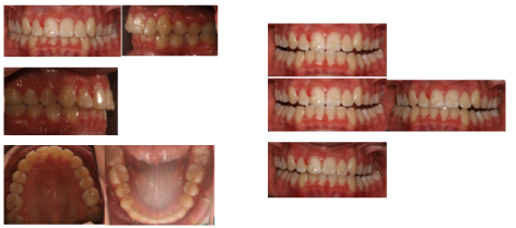
Figure 16. INTRAORAL FINAL PHOTOS
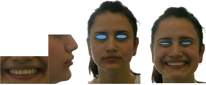
Figure 17. EXTRAORAL FINAL PHOTOS
Figure 18. FINAL CBCT IMAGES
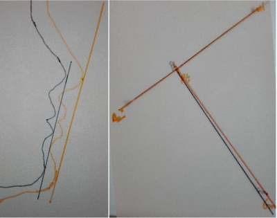
Figure 19. SUPERIMPOSITION (Na-Ba at CC) and PROFILE
Discussion
-Mandibular movements 2021 Copyright OAT. All rights reserv>
-Good face profile and teeth exposure during smile
-Good position of root between cortical alveolar bone (see cross sections)
-The root and palatal face of crown of tooth 2.2, are not regular
-Initial and final cefalometric values are not chenged so much. The mandible has moved forward and upper incisors inclination is increased
-Each condyle is placed in the center of its fossa
-Dental arch has a regular and wide form
-Wisdom teeth should be extracted
References
- Borgis KJ, Halsband H (1992) Three-dimensional evaluation of computerized tomography images of pediatric fractures. Langenbecks Arch Chir Suppl Kongressbd 1992: 390-395. [Crossref]
- Proffit WR, Frazier-Bowers SA (2009) Mechanism and control of tooth eruption: overview and clinical implications. Orthod Craniofac Res 12: 59-66. [Crossref]