Glaucoma is the second leading cause of vision loss in the world. We propose a novel, automated, appearance-based glaucoma classification system that does depend on segmentation-based measurements. It applies a standard pattern recognition process with a 2-stage classification step: To automatically extract the optic disc (OD), two methods making use of an edge detection method and Contours active Chan and Vese model are proposed in this paper. For the optic cup (OC) or excavation, inspection by the histogram is used to automatically detect the (OC). Our system SKVMs technique achieves 93% success rate on a data set containing a mixture of 75 real images of healthy and glaucomatous eyes. A set of 75 retinal images obtained from healthy and glaucomatous eyes, is used to assess the performance of the determined CDR to the clinical CDR, and it is found that our proposed method provides 98% accuracy in the determined CDR results and an early screening glaucoma by SKVMs approach that presented the aim of this paper.
Automated glaucomatous structures-screening, Circular Hough transform CHT, active contours Chan & Vese model, segmentation, Cup-to-disc ratio CDR, Classification, pattern recognition, Support vector machine SVM classifier
Abbreviations
A- ANN: Artificial network of neurons; ANOVA: Analysis of variance; C-CHT: Circular Hough transform; CDR: Cup-to-Disc ratio; COG: Concept centre of gravity; Df: Degree of freedom; Dice: The Dice index measures the similarity between two images d1 and d2 based on the number of regions common to d1 and d2; E-EOD: Examination of optic disc; EDA: estimation of distribution algorithms; F-FP: False positive; FN: False negative; FPT: The false positive rate; FBR: The basic radial function; FOV: The field of view; G-GPAO: Primary open-angle glaucoma; Gdx: The GDx is a tool that uses the laser to determine the thickness of the nerve fibre layer; H-HRT: retinal tomography of Heidelberg; HSD: “Honestly Significantly Different” test; I- ICE: Iridocorneal endothelium syndrome; ISNT: Lower-Upper-Nasal-Temporal; J-Jaccard: The index and the distance of Jaccard are two metrics used in statistics to compare the similarity and the diversity (in) between samples. They are named after the Swiss botanist Paul Jaccard. The Jaccard index or Jaccard coefficient [Jaccard, 1901] is the ratio between the cardinality (size) of the intersection of the sets considered and the cardinality of the union of the sets. It makes it possible to evaluate the similarity between the sets; K-KS: The Kolmogorov-Smirnov test; M- MSE: Mean square error; N-NTG: Glaucoma at normal tension; NIR: near infrared light (NIR); NPBS: Collimation to a non-polarizing beam splitter; O-OC: Optic Cup; OD: Optic Disc; OCT: ocular coherence tomography; ONH: Optic Nerve Head; P-PIO: Intraocular pressure; PBS: The polarizing beam splitter; PSG: the polarization state generator; PSD: The polarization state detector; PXF: pseudoexfoliative glaucoma, also called exfoliative glaucoma; R- ROI: Region of interest; RGB: Red_Green_Blue channels; ROC: The characteristic operating curve of the receiver; RBS: Renal Birefringence Scanning; S-SKVMs: Support kernel vector machines; SNR: Signal-to-noise ratio; Std: Standard deviation; SLO: Scanning Laser Ophthalmology; SLP: Scanning Laser Polarimetry (SLP); TN: True negative; TP: True positive; TSNIT: Temporal-Superior-Nasal Lower-temporal.
In this research paper, the aim was to identify, first and foremost, the theoretical generalities concerning the pathology of glaucoma, but also the techniques of digital image acquisition of the retina where the cup-disc excavation is located. the papilla beginning of the head of the optic nerve (Gdx; SLO, OCT ... .Scanning of the retina by a Laser signal); pathology detection parameters; use of digital techniques to limit and segment the area affected by the excavation of the disc which can lead to a total blindness of vision (Digital techniques will be cited later such as CHT), then I worked on a code of the circular Hough transform CHT written by a powerful languages (Matlab and C#) to automatically detect the coaxial contours of the optic nerve head and determine the severity of the excavation from where glaucoma by a ratio Cup / Disc horizontal and vertical automatically determined by a code written in Matlab language.
I added a script of an automatic contours detection code based on the level-set theory and Snake also written by the Matlab language, which in turn gave altruistic results to automatically calculate the ratio Cup-to-Disc and compare it to the threshold value 'cup / disc = 0.5' and systematically screen a patient with glaucoma or not.
The study of the development and extension of the cup area (Airecup = Airepattern cup) can judge the severity of glaucoma pathology and can still be used as a means of early detection of the disease.
Finally, a SKVMs classification technique was used which first came into contact with other classification methods such as ANN and showed its robustness in judging different classes of glaucoma.
As a result, we thought of introducing a hierarchical method based on:
- A circular / curvilinear segmentation which operates at the pixel level to form regions more or less homogeneous in the sense of the gray levels.
- Segment (merge) these obtained regions, by partitioning digital techniques of extraction of regions to form other more significant regions and larger and consistent in the sense of texture.
None of the merged regions really converge towards the deferent objects that can be discerned from the image, the second phase is reiterated several times with a particular adjustment of some regularization parameters, until the achievement of a stopping criterion. The approach was validated on the basis of ophthalmologist expert images on which it was quantified and compared to other existing algorithms.
Problem Statement: Glaucoma represents a significant health problem and is an important cause of blindness worldwide. Examination of the optic nerve head through cup-to-disc ratio is very important for the diagnosis of glaucoma and for monitoring the patient after diagnosis. The images of the optic disc (OD) and the optic cup (OC) are acquired by a fundus camera as well as by optical coherence tomography. Optic disc and optic cup segmentation techniques are used to separate relevant parts of the retinal image and to calculate the cup-to-disc ratio C / D and other features. The main objective of this paper is to review the methodologies and segmentation techniques for the disc and optic cup limits that are used to automatically calculate the geometric parameters of disk and cup with high accuracy to help glaucoma professionals to diagnose and detect pathology using images of the retinal fundus. We provide a brief description of each technique, highlighting its classification and performance measures. Current and future research directions are summarized and discussed.
Determining the cup-to-disc ratio is a very expensive and tedious task currently performed only by professionals. As a result, automated image detection and glaucoma assessment will be very useful. There are two different approaches to automatic image detection of the optic nerve head. The first approach is based on the very difficult process of extracting image characteristics for the binary classification of normal and abnormal conditions. The second, more frequent, approach is based on clinical indicators such as the cup-to-disc ratio as well as the inferior, superior, nasal and temporal areas (ISNT) in the area of the optic disc.
The main contribution of this paper is the introduction of a study of the current methods of segmentation of optical disc and optical cup for the calculation of the CDR and the excavation area used as parameters for automatic and early diagnosis of glaucoma before it reaches irreversible stages resulting in total blindness and loss of vision. Optical disc segmentation methods were first provided, followed by two optical cup segmentation methods. Finally, the optical disc with optical cup segmentation methods were covered. The main objective was to present some of the current methodologies of detection and segmentation and to give the professional an overview of the existing research. Current trends and challenges as well as future directions for the segmentation of optical disc and optical cup were also discussed.
STARE Dataset: The Structured Retinal Analysis (STARE) dataset is funded by the National Institutes of Health in the United States. The project has 400 fundus images. Each image is a diagnosis. The blood vessels are annotated in 40 images. The ONH is located in 80 images. A TopCon TRV-50 screen camera with a 35 ° field of view was used to capture images [1].
The optical disc OD is constituted of 1.2 million ganglion cell axons crossing the retina and out of the eye through the scleral channel for transmitting visual information to the brain. Examination of the optical disc can clarify the relationship between the excavation of the optic nerve and visual field loss in glaucoma [2]. The optic disc is divided into three different zones: the neuro-retinal edge, the cup (central zone) and sometimes the parapapillary atrophy [3]. The cup-to-disc ratio (CDR) is the ratio between the vertical diameter of the cup and the vertical diameter of the disc [4].
Various techniques have been used to extract the optic disc (OD), the optic cup (OC), or the optical disc with the segmentation of the optical cup. In this paper, we critically examine the OD and OC segmentation methodologies that automatically detect OD and OC boundaries. These techniques help professionals diagnose and monitor glaucoma by providing clear and accurate information about the structure of ONH. The individuality of this paper is to demonstrate the segmentation methodology by creating a flowchart for each technique. We present the algorithms applied to OD and OC segmentation, discuss the advantages and disadvantages of each method, and provide suggestions for future research.
Ophthalmologists generally acquire different imaging modalities to diagnose ocular pathologies. They include, for example, fundus photography, optical coherence tomography (OCT), computed tomography (CT) and magnetic resonance imaging (MRI). However, these images are often complementary and express the same pathologies in a different way. Certain pathologies are visible only in a particular modality. Thus, it is beneficial for the ophthalmologist to merge these modalities into a single patient-specific model.
The aim of the presented paper is a fusion of numerical and statistical approaches that can be applied to all retinal fundus images from different digital image acquisition modalities. This adds information to the fundus retinal image acquired from fundus photography that was not visible before, such as the vessels and the macula. The contributions of this purpose include the automatic detection of the optical disc, the optical cup, the fovea, the optical axis and an automatic segmentation of the area of the disc and the area’s cup [5].
A digital image that represents a scene of the real world (natural image) is cut into a matrix of elementary square cells (i.e., indecomposable) and characterized by a single color called pixel. The processing of these pixels (and more specifically the treatment of the luminance or color associated with each of them) defines what is called computer vision (Figure 1).
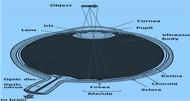
Figure 1. The human eye. The observed object is projected on the macula, whose central part is the fovea, the place of the clearest vision.
The cost of fundus photography continues to be significantly lower than the more recent retinal scanning techniques. Its main advantages are easy interpretation, color (helps to distinguish size and pallor), better detection of disc haemorrhage’s, peri-papillary atrophy, etc. The disadvantages are the lack of quantitative description and therefore the inter-observer variability, the highest photographic quality, always easily achievable. Another disadvantage of fundus photography is the need for a high light intensity for retinal illumination, in the order of 10 to 100% of the maximum allowable levels [6], typically delivered by a flash.
Risk factors
Elevated IOP in particular> 26 mmHg.
Myopia.
Diabetes.
Positive family history: Incidence increases from 2 to 4 for those with an affected sibling.
Ethnicity: Some ethnic groups have an increased incidence of glaucoma. People of Asian and Inuit (eskimo) origin have an increased incidence of angle-closure glaucoma (20 to 40 times in Inuit), but a low incidence of open-angle glaucoma. People of African descent are three times more likely to develop open-angle glaucoma [7].
Gender: Women are three times more likely than men to develop angle-closure glaucoma because of their shallow anterior chambers.
Prolonged use of steroids.
Conditions that severely restrict blood flow to the eye - for example, diabetic retinopathy, occlusion of the central vein of the retina.
Eye trauma.
Uveitis.
Systemic hypertension.
The emergence of open angle glaucoma is insidious and patients often do not know it. They can have a serious illness despite good visual acuity. Those who have a more advanced disease may be aware of a shadow in their vision or a decrease in visual acuity. However, a normal visual field in one eye may mask the presence of a defect in the affected eye until the disease is advanced enough.
The diagnosis of this silent disease is critical, if missed, the window of opportunity to stop progression may be lost. If the diagnosis is wrong, inappropriate medications can last a lifetime. In some cases, the diagnosis is obvious, especially with secondary glaucoma.
Patients with suspected glaucoma need a thorough eye exam to rule out co-pathology or other possible diagnoses. The ratings are the same for patients with glaucoma and those with - or suspected to have - eye hypertension.
Segmentation by multi-thresholding
Thresholding makes it possible to separate an image into antithetic components by transforming it into a binary image. This implies that the image is separated into white or black pixels depending on whether their intensity value is above or below a certain threshold. The thresholding process can be particularly useful for removing unnecessary detail or variations and highlighting the details of interest. An overall threshold value can be chosen automatically or on the basis of clear points in the image histogram that would allow effective separation. More complex intensity criteria can be used to assign whether pixel values become white or black. For some images, adaptive or local thresholding is useful when different thresholds are applied to different sections of the image, for example, the image at different levels of background lighting.
Keeping in mind human visual perception, extreme pixel values do not need to be finely quantified. By appropriate coarse graining, these can be progressively eliminated from the rest of the pixel values, which must be finely segmented. A recursive implementation produces non-uniform segmentation that naturally allows finer quantization around the mean. This procedure zooms in on the mean in a manner similar to approaching a variety of distributions to the Dirac delta function (Figure 2,3).
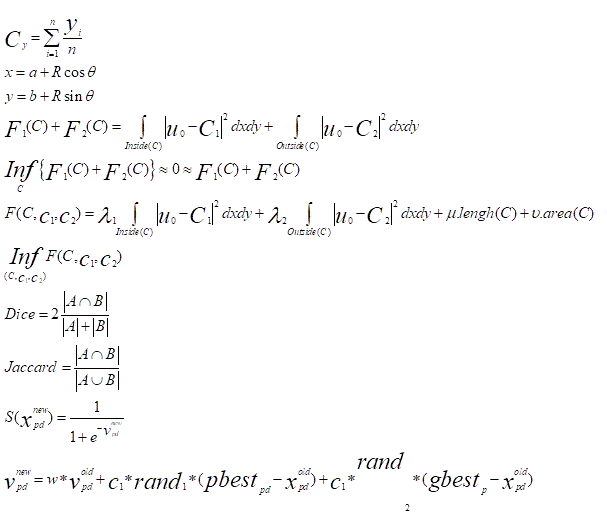
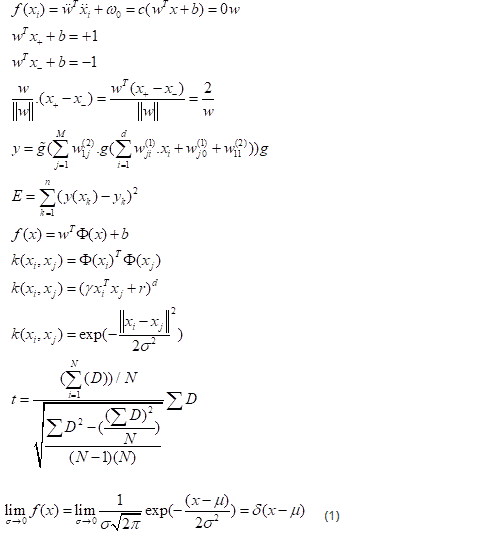
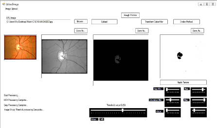
Figure 2. Technique multi_thresholoding written in C # determines more than one threshold for the particular image and segmenting the image by detecting the optical cup OC in certain brightness regions, which correspond to a background and more objects, T_value = 149.
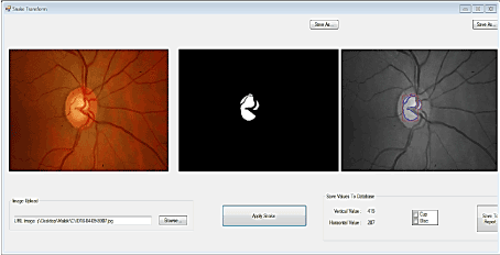
Figure 3. Results of the detection of the optical cup by the technique of multi-thresholding then used as starting image to detect the contours (blue lines) of different regions constituting the cup by application of the approach of active contours Chan & Veese model.
Extraction of sumptuous features of glaucoma
This study aims to automated optic disc (OD) and optic cup (OC) detection who plays an important role in developing a computer-aided system for eye glaucoma diseases. In this paper, we propose an algorithm for OD and OC detection based on structured learning. A classifier model is trained based on structured learning. Then we use the model to achieve the edge contour of OD and OC. Level-set is performed on the edge contour thus; a binary image of the OD and OC is obtained. Firstly, circle Hough transform is carried out to approximate the boundary of OD by a circle. Finally, active contours without gradient applied to the approximate boundary to accurately calculated the edge of the papilla [8, 9].
The proposed algorithm has been evaluated on two public datasets one for kids’ eyes, the other for adult’s eyes and obtained promising results. The results (an accuracy mean of 0.98, and a true positive and false positive fraction of 0.97 and 0.01) show that the proposed method is very competitive with the state-of-the-art methods and is a consistent tool for the segmentation of OD and OC to calculate, automatically, the cup-to-disc ratio CDR and for the extraction of others features to distinguish eye glaucoma diseases [10, 11].
Proposed methodology to classify glaucomatous of non-glaucomatous subjects: SKVMs
The proposed methodology implemented here is based on the concept of applying Feature Selection from the edge detection Dataset results (Output) and then classifying normal eyes and abnormal eyes (Glaucomatous subjects) based on enhanced decision (CDRV ≤ or ≥ 0.5).
- Load an input edge cup and disc detection Dataset.
- Apply CHT approach and active contours Chan-Vese approach-based Feature Selection and optimization is done using SKVMs for the Selection of most dependent attributes from the Dataset.
- Apply enhanced screen-based decision algorithm for the classification of glaucomatous Dataset [12, 13].
The hole is larger (excavation), corresponding to the loss of nerve fibers.
Early detection and subsequent treatment of glaucoma is hence important as damage done by glaucoma is irreversible. Large scale manual screening of glaucoma is a challenging task as skilled manpower in ophthalmology is low. Hence many works have been done towards automated glaucoma detection system from the color fundus images (CFI). In this paper, we propose a novel method of automated glaucoma detection from CFI using SKVMs approach. Structural features such as cup-to-disk ratio (CDR), cup area (CA) and disk area (DA) of the optic nerve head (ONH) are extracted from CFI using Circular Hough transform (CHT), level-set method, [6] inspection by histogram and morphological processing in order to segment Optic Disk (OD) and Optic Cup (OC) required for calculating the CDR value. The results obtained by the proposed methodology are very promising yielding an overall efficiency of 99 and rate classification of 93 obtained by SKVMs method to distinguish healthy from glaucomatous eye and in order to assist ophthalmologists.
To calculate the vertical cup to disc ratio (CDR) along the vertical axis and the horizontal axis, the optic cup and disc first have to be segmented from the retinal images. Figure 4 depicts the framework for building the proposed detection system.
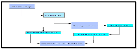
Figure 4. Retina image processing framework for cup-to-disc ratio (CDR) detection in glaucoma analysis.
The Cup-to-Disc ratio (CDR)
It evaluates horizontally and / or vertically at the larger diameter of the optical disc and the wider diameter of the excavation in the same axis. It is expressed in tenths (0/ 10 to 10/ 10) or 0.0 (no excavation) to 1.0 (when the excavation is total). It seems more relevant if one wants to keep that value, considering the C / D vertical: in glaucoma, the optic disc was first excavated more vertically than horizontally; and, in case of total excavation, vertical C / D is 10/ 10 ... that can be the horizontal C / D, because of the nasal vascular persistence of the emerging packet [14] (Figure 5).
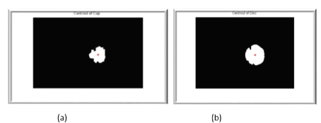
Figure 5. a) The computed centroid of optic cup into fundus retinal image b) The computed centroid of optic disc into fundus retinal image.
Region of Interest (ROI) and centroids detection (Cx, Cy)
If the Euclidean distance between two centroids is less than a specified threshold , these clusters are combined to one cluster.
The new centroid (Cx, Cy) is computed as:
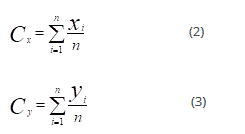
Where (Cx, Cy) is each cluster point and n is the number of points of the cluster.
Optic Disc Segmentation
To detect an optic disc boundary, image pre-processing is introduced.
To remove the blood vessels, a morphological closing operation is performed.
After performing the closing operation, a median filter is applied to further smoothen the obtained image. The outputs of the image pre-processing are shown in
After the image pre-processing is performed, two techniques combined and assembled for extracting a disc boundary are introduced: Circular Hough transform CHT and active contours without edges (gradient) CHAN & VESE Approach.
Circular Hough transform CHT approach
The detection efficiency is enhanced by the discretization of the image and the reduced resolution compared to the circle centre detection process and proves that the centre of the circle is on the gradient line edge point circle; meanwhile, the beam detection accuracy is improved by merging the similar radius within the range of detection process.
The circle Hough Transform (CHT) is a feature extraction technique for detecting circles. It is a specialization of Hough Transform. The purpose of the technique is to find circles in imperfect image inputs. The circle candidates are produced by voting in the Hough parameter space and then select the local maxima in a so-called accumulator matrix [15].
Pseudo code for feature selection process using CHT
Pseudocode:
i=0
For all the coordinate pixels ‘’a’’ and ‘’b’’ of the binarized image
| If the current pixel belongs to a circular contour
| | For all other x and y coordinate pixels in the image | | radius = (x-a)2 + (y-b)²
| | | If radius is equal to the desired radius
| | | | detec_circle[i]. val++
| | | | detec_circle[i]. a = a
| | | | detec_circle[i]. b = b
| | | | detec_circle[i]. radius = radius
| | | | i++
| | | end
| | end
| end
end
The circular Hough transform applied at the retinal image can in some cases simultaneously detects the optic disk and the head of the optic nerve cup as shown in the following figure (Figure 8,9).
Figure 6. Result of the combination of the two techniques CHT and Active contours Van & Chese.
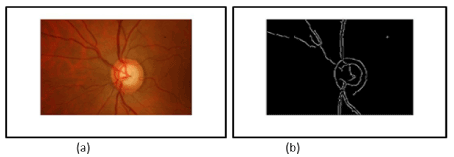
Figure 7. a) Input resize Image (rf =0.125) + Red channel component b) edge Canny results after Closing operation and Median filter applying on the input resize image.
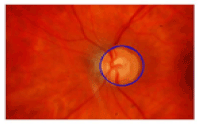
Figure 8. Optic disc detection (OD) using computed Hough circle by voting number ‘’n’’.
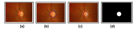
Figure 9. a) Input resize image b) Optic Disc Detection by applying the CHT c) Optic Cup detection by applying the CHT d) ROI of cup calculated only by applying the CHT on the input resize image.
The Hough transform can be used to determine the parameters of a circle when a number of points that fall on the perimeter are known. A circle with radius R and centre (a , b) can be described with the parametric equations:
x = α + R cos θ (4)
y = b + R cos θ (5)
Active contours approach without gradient Chan & Vese model
The Active contour method without gradient algorithm has been widely used as a global approach for the optimization of active contours for the segmentation of objects of interest from the background. In this study, this method is employed by initializing a curve centred at the detected optic disc location. The curve is evolved based on the average intensity value inside and outside the curve. The curve evolution always converges to the optic disc edge irrespective of the shape or size of the initial contour.
The basic idea in active contour models or snakes is to evolve a curve, subject to constraints from a given image, in order to detect objects in that image. For instance, starting with a curve around the object to be detected, the curve moves toward its interior normal and has to stop on the boundary of the object.
Assume further that the object to be detected is represented by the region with the value ui0 and let denote his boundary by C.
Then we have u0 ≈ ui0 inside the object (inside C) and u0 ≈ uo0 outside the object (outside C). Now let us consider the following” fitting energy”, formed by two terms:

where C is any other variable curve. We say that the boundary of the object ζ is the minimizer of the F fitting energy:

This can be seen easily. For instance, if the curve C is outside the object, then F1(C) > 0 and F2(C) ≈ 0. If the curve C is inside the object, then F1(C) ≈ 0 but F2(C) > 0. Finally, the Fitting energy will be minimized if the C = ζ, i.e. if the curve C is on the boundary of the object.
Therefore, in our active contour model we will minimize this fitting energy and we can add some regularizing terms, like the length of C and/ or the area inside C. We introduce the energy F(C,C1,C2) by:
 (8)
(8)
where c1 and c2 are constant unknowns, and λ₁, λ₂ > 0, μ > 0, υ ≥ 0 are fixed parameters.
In almost all our computations, we take υ = 0 and λ₁= λ₂. Of-course that one of these parameters can be removed, by fixing it to be 1. In almost all our computations, we take υ = 0 and λ₁= λ₂.
The area term in the energy can be used for instance when we may need to force the curve to move only inside.
Finally, we consider the minimization problem: 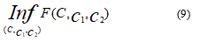
Optic Cup Segmentation
Compared to the extraction of the optic disc, optic cup segmentation is more rigid due to a cup inter weavement with blood vessels and surrounding tissues. This study presents two simultaneous steps approaches for cup segmentation, which are the inspection by histogram approach and detection’s cup by applying the active contours CHAN & VESE approach.
The histogram is a fundamental image analysis tool that describes the distribution of the pixel intensities in an image. Use the histogram to determine if the overall intensity in the image is high enough for our inspection task. We use the histogram to determine whether an image contains distinct regions of certain grayscale values.
Lack of contrast—A widely-retina image contains a lack of contrast between cup and disc, there’s why in our type of imaging application involves inspecting and counting parts of interest in a background of retina. (Figure 10)
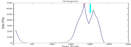
Figure 10. The normalized cumulative histogram used to detect (OC).
This region presents our area of interest and contains the optic cup (OC) with maximum intensity (red dot form) and the optic disc (OD) with a more moderate intensity (green dot form).
To separate the two regions and finally detect the Cup we use the threshold of technical inspection by the histogram. ROI by thresholding referring to the peak value calculated we obtain our Cup segmented as shown in the following figures (Figure 11).
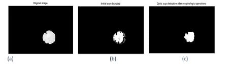
Figure 11. a) Input image b) Input Cup detected c) Morphological opening operation and final cup detection.
To evaluate the performance of our approach, we used more than 65 fundus images from glaucomatous and non-glaucomatous cases taken from the following database:
Site1 : http:/ / cecas.clemson.edu/ ~ahoover/ stare/
The images were acquired with a color analogical fundus camera, approximately centred on the ONH and they were stored in slide format. In order to have the images in digital format, they were digitized using a HP-PhotoSmart-S20 high-resolution scanner, RGB format, resolution 600x400 and 8 bits/ pixel.
To assess classifier performance, it is necessary to quantify the sensitivity, specificity and accuracy.
In glaucomatous classification problem, sensitivity measures the accuracy of the classifier to identify glaucoma in the set of fundus images, and specificity measure the accuracy of classifiers for identifying healthy people in the set (Figure 12).
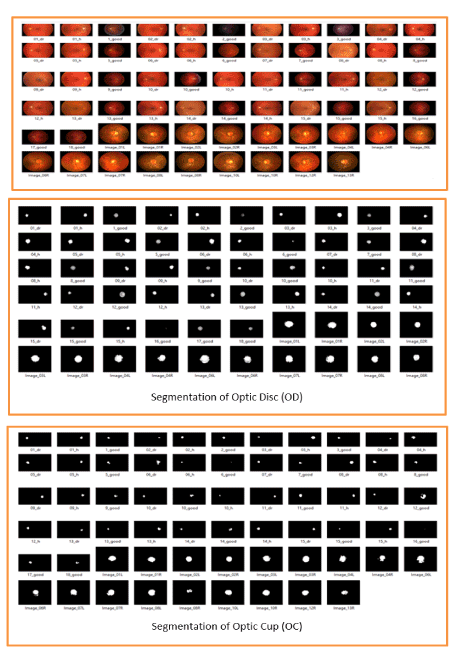
Figure 12. a part of dataset used to detect the Cup and the disc in the papilla and extract the sundry features results of glaucoma disease.
The average value of the specificity and the sensitivity using our approach to detect glaucomatous is 99%. At this point, the set of 75 test images are processed using the approach outlined earlier in order to obtain the CDR value, CDR Automated, and the area of the optic cup (excavation), Area Automated.
Then applying different parameters for assessing the diagnostic of glaucoma, we obtain the compared results prepared in the following table 1-4, Figure 13.
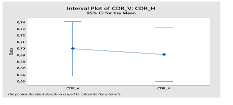
Figure 13. Concatenation of the CDRV and CDRH values shown in Table 1 to determine its mean values for a CI confidence interval = 95%.
The correlation between CDRv and CDRH is quite strong, whereas the correlations between the different others features two by two is almost total and strong (the correlation coefficient r is almost equal to 1) as mentioned in the following table 2, Figures 14, 15.
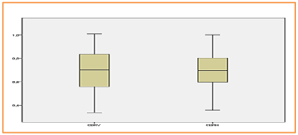
Figure 14. BOXPLOT EXAMINE VARIABLES= CDRV & CDRH /Mean values respectively: 0,6995 & 0,6908.
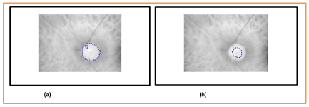
Figure 15. a) Optic Disc (OD) boundaries assessed and b) annotated by a senior ophthalmologist.
Table 1. CDR Metric values obtained after the calculus of the cup and disc diameter along vertical & horizontal axis.
- Cup Diameter and Disc Diameter longitudinal & transversal *Values in pixel unit.
- Area Cup and Area Disc**Values in pixel2 unit.
- CDV: Cup Diameter Vertical; _CDH: Cup Diameter Horizontal.
- DDV: Disc Diameter Vertical; _DDH: Disc Diameter Horizontal.
- CDR: Cup-to-Disc ratio.
Image |
Area cup AC |
Area disc AD |
Area ratio AR |
Diam cupV DCV |
Diam discV DDV |
CDR_V |
Diam cupH DCH |
Diam discH DDH |
CDR_H |
'01_dr.JPG' |
1093 |
1627 |
0,671788568 |
40 |
50 |
0,8 |
34 |
44 |
0,772727273 |
'01_h.jpg' |
1312 |
2074 |
0,632594021 |
45 |
54 |
0,833333 |
40 |
52 |
0,769230769 |
'02_dr.JPG' |
409 |
968 |
0,422520661 |
20 |
35 |
0,571429 |
20 |
32 |
0,625 |
'02_h.jpg' |
1150 |
1896 |
0,606540084 |
42 |
47 |
0,893617 |
30 |
46 |
0,652173913 |
'03_dr.JPG' |
694 |
1731 |
0,400924321 |
37 |
49 |
0,755102 |
32 |
43 |
0,744186047 |
'03_h.jpg' |
2250 |
3647 |
0,616945435 |
52 |
68 |
0,764706 |
59 |
66 |
0,893939394 |
'04_dr.JPG' |
461 |
1806 |
0,255260244 |
27 |
47 |
0,574468 |
20 |
46 |
0,434782609 |
'04_h.jpg' |
1853 |
3691 |
0,50203197 |
51 |
77 |
0,662338 |
49 |
61 |
0,803278689 |
'05_dr.JPG' |
1440 |
3143 |
0,458160993 |
40 |
68 |
0,588235 |
43 |
60 |
0,716666667 |
'05_h.jpg' |
1101 |
3637 |
0,302722024 |
45 |
72 |
0,625 |
29 |
70 |
0,414285714 |
'06_dr.JPG' |
2406 |
4479 |
0,537173476 |
67 |
86 |
0,77907 |
42 |
67 |
0,626865672 |
'06_h.jpg' |
402 |
1876 |
0,214285714 |
22 |
51 |
0,431373 |
21 |
53 |
0,396226415 |
'07_dr.JPG' |
1013 |
2307 |
0,439098396 |
39 |
59 |
0,661017 |
27 |
54 |
0,5 |
'08_dr.JPG' |
2186 |
4459 |
0,490244449 |
53 |
79 |
0,670886 |
52 |
76 |
0,684210526 |
'08_h.jpg' |
1652 |
3123 |
0,528978546 |
50 |
59 |
0,847458 |
38 |
66 |
0,575757576 |
'09_dr.JPG' |
1182 |
2676 |
0,441704036 |
41 |
65 |
0,630769 |
37 |
46 |
0,804347826 |
'09_h.jpg' |
1123 |
2709 |
0,414544112 |
37 |
59 |
0,627119 |
38 |
53 |
0,716981132 |
'10_dr.JPG' |
844 |
1601 |
0,527170518 |
36 |
43 |
0,837209 |
28 |
47 |
0,595744681 |
'10_good.JPG' |
1677 |
4360 |
0,384633028 |
29 |
79 |
0,367089 |
53 |
78 |
0,679487179 |
'10_h.jpg' |
405 |
1444 |
0,280470914 |
22 |
49 |
0,44898 |
21 |
41 |
0,512195122 |
'11_dr.JPG' |
747 |
2105 |
0,354869359 |
31 |
48 |
0,645833 |
29 |
53 |
0,547169811 |
'11_good.JPG' |
2109 |
6298 |
0,334868212 |
54 |
102 |
0,529412 |
46 |
77 |
0,597402597 |
'11_h.jpg' |
1177 |
2186 |
0,538426349 |
43 |
55 |
0,781818 |
31 |
51 |
0,607843137 |
'12_dr.JPG' |
752 |
1777 |
0,423185144 |
32 |
53 |
0,603774 |
30 |
44 |
0,681818182 |
'12_good.JPG' |
4524 |
7309 |
0,618962922 |
81 |
99 |
0,818182 |
62 |
92 |
0,673913043 |
'12_h.jpg' |
980 |
2624 |
0,37347561 |
39 |
56 |
0,696429 |
31 |
58 |
0,534482759 |
'13_dr.JPG' |
857 |
2695 |
0,317996289 |
33 |
65 |
0,507692 |
29 |
54 |
0,537037037 |
'13_good.JPG' |
921 |
5720 |
0,161013986 |
31 |
92 |
0,336957 |
36 |
81 |
0,444444444 |
'13_h.jpg' |
1566 |
3531 |
0,443500425 |
45 |
69 |
0,652174 |
46 |
65 |
0,707692308 |
'14_dr.JPG' |
839 |
1894 |
0,442977825 |
35 |
48 |
0,729167 |
30 |
50 |
0,6 |
'14_good.JPG' |
1694 |
5376 |
0,315104167 |
36 |
89 |
0,404494 |
33 |
79 |
0,417721519 |
'14_h.jpg' |
1435 |
2787 |
0,514890563 |
43 |
60 |
0,716667 |
40 |
58 |
0,689655172 |
'15_dr.JPG' |
1058 |
3276 |
0,322954823 |
38 |
72 |
0,527778 |
37 |
59 |
0,627118644 |
'15_good.JPG' |
466 |
2594 |
0,179645335 |
30 |
57 |
0,526316 |
20 |
56 |
0,357142857 |
'15_h.jpg' |
1128 |
1784 |
0,632286996 |
36 |
52 |
0,692308 |
36 |
44 |
0,818181818 |
'16_good.JPG' |
93 |
190 |
0,489473684 |
12 |
22 |
0,545455 |
7 |
15 |
0,466666667 |
'17_good.JPG' |
1543 |
4728 |
0,326353638 |
44 |
83 |
0,53012 |
46 |
77 |
0,597402597 |
'18_good.JPG' |
1306 |
2875 |
0,45426087 |
44 |
60 |
0,733333 |
45 |
60 |
0,75 |
'1_good.JPG' |
1826 |
6934 |
0,263340063 |
45 |
101 |
0,445545 |
47 |
93 |
0,505376344 |
'2_good.JPG' |
2247 |
4593 |
0,48922273 |
56 |
78 |
0,717949 |
54 |
74 |
0,72972973 |
'3_good.JPG' |
2015 |
5232 |
0,385129969 |
51 |
74 |
0,689189 |
60 |
84 |
0,714285714 |
'5_good.JPG' |
1550 |
4585 |
0,338058888 |
38 |
74 |
0,513514 |
43 |
77 |
0,558441558 |
'6_good.JPG' |
269 |
948 |
0,283755274 |
17 |
40 |
0,425 |
20 |
33 |
0,606060606 |
'7_good.JPG' |
1278 |
3292 |
0,388213852 |
36 |
61 |
0,590164 |
44 |
65 |
0,676923077 |
'8_good.JPG' |
1543 |
4728 |
0,326353638 |
44 |
83 |
0,53012 |
46 |
77 |
0,597402597 |
'9_good.JPG' |
1306 |
2875 |
0,45426087 |
44 |
60 |
0,733333 |
45 |
60 |
0,75 |
'Image_01L.jpg' |
9087 |
12707 |
0,715117652 |
101 |
123 |
0,821138 |
116 |
142 |
0,816901408 |
'Image_01R.jpg' |
8900 |
12853 |
0,692445343 |
100 |
113 |
0,884956 |
110 |
142 |
0,774647887 |
'Image_02L.jpg' |
7915 |
7920 |
0,999368687 |
105 |
106 |
0,990566 |
91 |
91 |
1 |
'Image_02R.jpg' |
7574 |
7628 |
0,992920818 |
100 |
102 |
0,980932 |
91 |
91 |
1 |
'Image_03L.jpg' |
9673 |
12729 |
0,759918297 |
115 |
129 |
0,891473 |
108 |
131 |
0,824427481 |
'Image_03R.jpg' |
10506 |
12320 |
0,85275974 |
125 |
133 |
0,93985 |
99 |
125 |
0,792 |
'Image_04L.jpg' |
9672 |
13450 |
0,719107807 |
118 |
129 |
0,914729 |
93 |
124 |
0,75 |
'Image_04R.jpg' |
7586 |
10701 |
0,70890571 |
114 |
121 |
0,942149 |
85 |
121 |
0,702479339 |
'Image_06L.jpg' |
12181 |
16895 |
0,720982539 |
141 |
148 |
0,952703 |
117 |
146 |
0,801369863 |
'Image_06R.jpg' |
8207 |
11834 |
0,693510225 |
97 |
124 |
0,782258 |
89 |
120 |
0,741666667 |
'Image_07L.jpg' |
9504 |
11906 |
0,798252982 |
110 |
127 |
0,866142 |
96 |
110 |
0,872727273 |
'Image_07R.jpg' |
11018 |
13459 |
0,818634371 |
120 |
132 |
0,909091 |
102 |
115 |
0,886956522 |
'Image_08L.jpg' |
10783 |
10830 |
0,995660203 |
124 |
123 |
1,00813 |
105 |
107 |
0,981308411 |
'Image_08R.jpg' |
3880 |
9169 |
0,423165013 |
50 |
115 |
0,434783 |
80 |
99 |
0,808080808 |
'Image_10L.jpg' |
9364 |
11949 |
0,783663905 |
106 |
128 |
0,828125 |
115 |
116 |
0,99137931 |
'Image_10R.jpg' |
10096 |
10202 |
0,98960988 |
115 |
115 |
1 |
110 |
113 |
0,973451327 |
'Image_12R.jpg' |
8403 |
10029 |
0,837870176 |
100 |
108 |
0,925926 |
102 |
117 |
0,871794872 |
'Image_13R.jpg' |
6440 |
8914 |
0,722459053 |
72 |
102 |
0,705882 |
99 |
109 |
0,908256881 |
Table 2. Paired Samples Correlations
|
N |
Corrélation |
Sig. |
Pair 1 |
CDRV & CDRH |
64 |
0,691 |
0,000 |
Pair 2 |
AreaCup & AreaDisc |
64 |
0,953 |
0,000 |
Pair 3 |
DiamCupVert & DiamDiscVert |
64 |
0,903 |
0,000 |
Pair 4 |
DiamCupHor & DiamDiscHor |
64 |
0,936 |
0,000 |
Table 3. Descriptive Statistics
|
N |
Minimum |
Maximum |
Mean |
Std. Deviation |
DiamCupHor |
64 |
7,00 |
117,00 |
54,9063 |
30,97706 |
DiamDiscHor |
64 |
15,00 |
146,00 |
75,8750 |
30,87790 |
Valid N (listwise) |
64 |
|
|
|
|
Table 4. Summary of the ANN model
Training |
Sum of Squares Error |
1,365 |
Relative Error |
0,062 |
Stopping Rule Used |
1 consecutive step(s) with no decrease in errora |
Training Time |
00:00:00,232 |
Testing |
Sum of Squares Error |
1,051 |
Relative Error |
0,337 |
Evaluation study
Our objective is to show that our multimodal evaluation method is effective, not to validate any method used here, so the methods used are not significant.
The methods chosen to carry out the study are:
- Method of detecting the papilla by the circular Hough transform, (CHT).
- Parametric classification using an active contour level set method compared to a manual classification performed by an ophthalmologist. Field model, (Chan_Vese model / Manual method).
- -Automatic learning of glaucomatous suspects using kernel vectors machines support, (SKVMs).
- Segmentation and merge segmentation, (SF).
As we said, in this work we use images from the bottom of the retina. The volume used has been pre-processed to eliminate noise and uninteresting areas.
We show in Figure 16, the segmentation results for a retinal background image, using the red channel for RGB. Overlap between OD manual and OD automated is represented in gray and square dots. There is no overlap between manual OC and automated OC in the region of interest (Figure 16-18).
Figure 16. The overlap between the CHT method and the segmentation manipulated by an expert ophthalmologist used to calculate the Dice parameter. Dice = 94%.
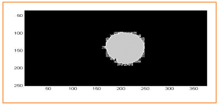
Figure 17. Overlap between the active contour method and the segmentation handled by an expert ophthalmologist used to calculate the Dice parameter. Dice = 97%.
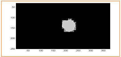
Figure 18. Overlap between the CHT_Contour active_Inspection by histogram and the segmentation method manipulated by an expert ophthalmologist used to calculate the Dice parameter. Dice = 93%.
For the evaluation of automatic segmentation of the disc and excavation 20 retinal images were both manually and automatically segmented. To evaluate the accuracy, the commonly used DICE similarity coefficient [16] was measured between manual and automatic segmentation calculated with different approaches. Similarly, Jaccard's index [17, 18] has been calculated. The coefficients DICE and Jaccard are respectively defined as:
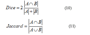
Where A∩B denotes the intersection between A and B, and A∪B denotes the union between A and B, and JC, DM∈ [0,1]. A higher value of JC or DM indicates a closer match between the manually delimited reference and the automatically segmented results.
Overall, the DICE coefficient resulted in 0.975 ± 0.005. The deviations from manual segmentation were mainly in the part using the CHT approach. Segmentation takes less than 2 seconds on a laptop.
Distinguish of glaucomatous eye from healthy eye by applying a kernel support kernel vector machines SKVMs
A supervised automatic learning algorithm SKVMs
The suspect stage is important because a patient will receive a warning and treatment before the excavation progresses and has symptoms such as headaches due to abnormal pressure inside the eyeball. In the clinic, the intraocular pressure is tested first. After that, an image of the fundus is taken to observe certain abnormalities in the retina. This provides important information to extract, such as the shape and asymmetry of the optical disk (OD), the size and depth of the optical cup, the vertical cup-to-disk ratio CDRv, the fibre layer anomalies. nervous and peripapillary atrophy. If some anomalies appear, the loss of visual field is determined. This can appear in one or both eyes. These abnormalities can be caused by many factors, but glaucoma is one of the risk factors that damages ONH and gradually leads to vision loss. In our hospitals, there is a shortage of ophthalmologists, technicians, health care workers and early treatment.
This system would help narrow the gap between these problems by providing an automatic screening system to diagnose the disease based on a supervised learning technique.
For the supervised learning technique, a characteristic of the target class must be extracted in order to generate a decision function or a model to classify each stage of the disease. In this work, segmentations OD and OC are considered. There are several techniques provided in previous work.
Correlation or similarity of characteristics should be evaluated to reduce redundant functionality. The dimension of characteristics can be reduced by techniques such as principal component analysis and linear regression. For the classification part, the classifiers that are normally used include K-mean, Cmeans fuzzy clustering [19], Bayesian technique, neural network (NN) [20, 21], Support vector machine (SVM), [22, 23]. Of these, NN and SVM provide high performance and robustness for higher classification sizes.
The ratio of OC to OD in the vertical direction (CDRv) is considered an important feature to check the abnormality of a retina using a fundus image.
In addition, the Rim-Disc 3 report was also proposed to be considered for special cases with
OC and OD but the tissues of healthy rim. Using only CDRv as a threshold to indicate glaucoma and non-glaucoma linearly is inadequate because there are overlapping values, which must be analysed in a higher dimensional space. For example, CDRv at 0.65 as the cut-off for glaucoma and non-glaucoma provides 80% accuracy, or 21 false negative (FN) and 3 false positive (FP) cases (Figure 19).
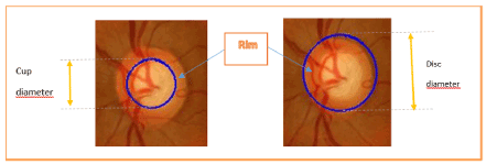
Figure 19. An image example of an ophthalmologist. A right blue line shows a contour of a disc ; a left blue line shows a contour of the excavation (Cup).
In this paper, we use the OC and OD diameters and the CDR in the vertical (CDRv) and horizontal (CDRH) directions as well as other features such as the excavation area. There are two case studies. In Case Study A, a comparison between previous work [23] and the proposed techniques is discussed. The FN and the FP must be reduced, therefore, the SVM is introduced into a classification process, diagnosed in two classes: healthy and glaucoma.
In case study B, the suspect stage of glaucoma is added. This is the step between normal classes and glaucoma classes. Early detection can be detected based on this suspicious class.
The number of false detections is also an important parameter for analysing the performance of the classification. At the polynomial degree three, the SVM kernel function is selected to generate the decision module that can reduce the number of false detections.
The SVM classification technique
The classification technique is widely used for prediction based on known characteristics from the database. An SVM technique is selected as a classifier to find a decision function. It can generate an adaptive decision limit, based on the distribution of selected information or features such as the CDR which is calculated from the ratio of the OC to the OD. Feature selection is required to use the kernel function to find the hyper optimal plan for separating the two classes.
First, the binary classification in Case Study A is described in detail. An SVM is widely used to classify an entity into a large feature space.
It provides several types of kernel functions (decision limits) such as linear, polynomial and radial basic functions. These kernel functions have different characteristics and kernel selection depends on the distribution of input information. An SVM with a linear kernel function is selected for Case Study A. SVM transforms two-dimensional input features into a higher dimensional feature space and maximizes sample distances (support vectors) from the plane hyper decisional. To calculate the maximum margin of the support vectors, the core function is represented by the Euclidean internal product [24, 25].
Here are the expressions of two selected kernel functions, KL (x, y)xTy for the default linear kernel and KP (x, y)(xTy + c)d for the polynomial kernel, where c 0 and d are parameters that can be adjusted to find the most efficient kernel function. The cost factor for the linear and polynomial kernel is fixed at 1.
Based on the experiences of case studies A and B, the weights of the selected entities are classified as follows; CDR, CDRH, D.Cup_V, D.Cup_H, D.Disc_V, D.Disc_H, Cup Area and Disk Area of the disc. In Case Study A, the parameters of the learning process are defined.
First, 9 features are extracted from 75 training samples. They are separated into two classes and labeled 0 for the target class and 1 for the others. An SVM is used and a classifier is generated. The K-fold cross-validation technique is selected to test accuracy. K is set to 10, then K - 1 divisions are driven. The test set randomly selected 10 of the dataset. The remaining 90 is assigned as training data. After the first ten percent has been tested, the following test data is modified to form a new, non-overlapping set. This procedure is repeated ten times until the last test. Then, global errors are accumulated and described in a matrix confusion.
Secondly, the multiple classification in case study B is described by introducing an SVM against rest and unbalanced decision tree with SVM in order to overcome a limitation of the traditional SVM, which is effective only in binary classes.
The multi-class SVM is used to distinguish three different data classes, 20 normal samples, suspect 15 samples, and glaucoma 40 samples. The following paragraph describes the classification model for each technique. The highest score is chosen, setting 0 for correct prediction and 1 for incorrect prediction.
The following vector shows a set of input characteristics used in the previous case study.
Features = [Cup_V, Disc_V, CDRv, Cup_H, Disc_H, CDRH]
Why SKVMs?
SVM is an automatic classification method [26, 27] that directly minimizes classification error without requiring a statistical data model. This method is popular because of its simple implementation and its consistently high classification accuracy when applied to many real classification situations. The SVM algorithm can be applied to both classification and regression (model adjustment) issues. In the classification, an SVM classifier can separate the data (for example, CDR calculation results from healthy and glaucomatous eyes) that are not easily separable into the original data space (i.e., two-dimensional x, y) by mapping the data into a larger dimension space. SVM uses a kernel function to find a hyperplane that maximizes the distance (margin) between the two classes (e.g., healthy eyes versus glaucomatous), while minimizing the training error [28]. The resulting model is scattered, relying only on a few training samples (the “Support Vectors”). The number of support vectors increases linearly with the available training data, [29] requiring much higher computational complexity when classifying very large data sets (for example tens or hundreds of thousands of variables).
SKVMs have been used by us and others for a variety of classification applications in clinical medicine, including detection, [30-33] and glaucoma prediction [29], detection of central auditory processing disorder, [34] detection of onset of seizures, [35] and detection [36] and characterization [37] of breast lesions.
SVM was implemented using Platt's minimal sequential optimization algorithm in commercial software (MathLab, version 5.0, The MathWorks, Natick, MA). For the classification of CDR data, Gaussian (non-linear) cores of different widths were tested, and a Gaussian kernel of width = √ (2 × number of input variables) was chosen to give the largest area under the ROC curve. Using cross validation 10 times. The penalty for the error margin / C margin was 1.0.
Application of SKVMs
This linear classifier determines a hyper-plane with maximum and soft margin that best separates the classes considered. The data is normalized and transformed via the nonlinear radial base kernel.
We use the -SVM with the penalty parameter ʋ0.5 and the cost parameter c1 [38].
Classifiers: The ability of each image-based feature extraction method to distinguish normal eyes from those with glaucoma is quantified by the results of three classifiers. Classifiers perform well if their underlying separation model matches the distribution of the sample data. As the distribution of the underlying data is unknown, we have tested different classifiers and we use in this article the support vector machine as a linear classifier [39, 40].
The distribution of attribute data may not optimally match the data model of the classifiers. We analyse the effect of two known methods to improve the result of the classification [41, 42].
The two-step classification applies the glaucoma class probability score, obtained from each of the four classifiers, as a new feature vector entering another classifier [43, 44]
Support kernel vector machines SKVMs
This linear classifier determines a maximum-margin and soft hyper-plane that best separates the considered classes. The data is normalized and transformed via the non-linear radial basis kernel.
We use the ʋ-SVM with penalization parameter ʋ = 0.5 and cost-parameter c = 1 [45].
Pseudo code for feature selection process using levelset based SKVMs
Start with the Initialization of Dataset results
While! (Ngen || Sc)
For p=1: Np
If qualification Xp (CDRv)> qualification pbestp = 0.5
Update pbestp = Xp
For 𝑘 ∈ NXp
If qualification Xk(CDRH)>gbest
Update gbest = Xk
Next K
For each dimension d
𝑣pdnew = 𝑤∗𝑣𝑝dold +𝑐1 * rand1 * (pbestpd –𝑥 oldpd ) + 𝑐2 * rand2 * gbestd _ 𝑥 oldpd )
If 𝑣𝑝d ∉ (𝑉𝑚in, 𝑉𝑚ax)
𝑣𝑝=max (min (𝑉max, 𝑣𝑝d), 𝑉𝑚in)
𝑥𝑝d = 𝑥𝑝d + 𝑣𝑝d
Next d
Next p
Next generation till stop
The method iteratively applies one arbitrary classifier. SKVMs Boosting is able to improve results especially of weak learners on real-world data and is robust to overfitting [46-49].
2-stage classification applies the probability score of belonging to the glaucoma class, obtained from each of the four classifiers, as new feature vector Input to another classifier [50, 51].
Methodology using SKVMs
The features are first encoding into a bit string S=CDRv1, CDRv2…. CDRv n, n=1,2…m and the bit {1} represents for the selected feature from the dataset and the bit string {0} is the non-selected feature from the dataset. The evaluation parameters can be computed using SKVMs. Let us suppose that in the dataset the accessible feature set is 65 then set {CDRv 1 CDRv 2 CDRv 3…. CDRv 65} is then analysed using SKVMs algorithm and selection of any number of features say 65 a dimensional evaluation of these 65 features is computed using SKVMs. Each feature is renewed using adaptive computation of SKVM, hence based on which pbest is chosen. Now for the final feature selection each of the vector is then updated according to operation [52, 53].
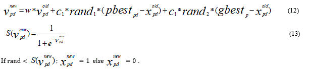
The renewed features are then calculated using Eq.12 and hence on the basis of renewal calculation of ‘S’ and depending on the previous value of ‘S’ the features are selected as {1} otherwise {0} means the feature is not selected.
The random feature selected assumes to be the best attribute of the dataset and so is the qualification value as best and selection of features starts from this feature of the dataset.
The feature to be selected moves along ‘X’ and ‘Y’ axis for the next best feature from the dataset depending upon the qualification value. Hence, initialize the Input parameters of SKVMs.
The selection of features starts with the basic input to SKVMs as the training values and class index.
On the basis of Training Parameters as (trnX, trnY, tstX, ker), Selection of ‘Y’ as the features values can be predicted.
A predefined function is defined which computes the features based on above parameters [54-59].
Binary Classification
Given training data (xi, yi) for i = 1. . . N, with xi ∈ Rd and yi ∈ {−1, 1}, learn a classifier f(x)
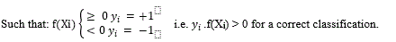
Linear separability
A linear classifier has the form: 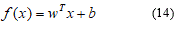
For example, X1 = CDRV and X2 = CDRH.
• In 2D the discriminant is a line
• xi is the normal to the line, and b the bias
• w is known as the weight vector
For a K-NN classifier it was necessary to ‘carry’ the training data and for a linear classifier, the training data is used to learn w and then discarded. Only w is needed for classifying new data [56, 57] (Figure 20).
Figure 20. Configuration indicate a form of linear classifier.
Given linearly separable data xi labelled into two categories yi = {-1,1}, find a weight vector w such that the discriminant function: 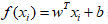 separates the categories for i = 1, and to find this separating hyperplane, we proceed with the perceptron Classifier:
➞ Initialize w = 0
➞Cycle though the data points {xi, yi }
➞If xi is misclassified then w 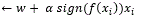
➞Until all the data is correctly classified [58, 59].
Since 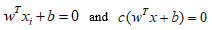 define the same plane, we have the freedom to choose the normalization of W.
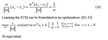
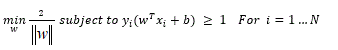
Choose normalization such that 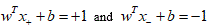 for the positive and negative support vectors respectively. Then the margin [30] [31] is given by:
Comparison of SKVMs and ANN: Support vectors of machines SVM against ANN artificial neural networks
The development of ANNs has followed a heuristic path, with applications and extensive experimentation preceding the theory. On the other hand, SVM development involved sound theory first, followed by implementation and experiments. An important advantage of SVM is that if ANN can suffer from several local minima, the solution to an SVM is global and unique. Two other advantages of SVM are that they have a simple geometric interpretation and give a sparse solution. Unlike ANNs, the computational complexity of SVMs does not depend on the dimensionality of the input space. ANNs use empirical risk minimization, while SVMs use structural risk minimization. The reason that SVMs often outperform ANNs in practice is that they deal with the biggest problem with ANNs, SVMs are less likely to adjust.
“Most often, Gaussian kernels are used, when the resulting SVM corresponds to an RBF network with Gaussian radial basic functions, because the SVM approach solves” Automatically “the problem of network complexity, the size of the hidden layer The concealed neurons and the support vectors correspond to one another, so that the central problems of the RBF network are also solved because the support vectors serve as basic function centres.'' Horváth (2003) in Suykens et al. ''
Results given by application of ANNs
Conventional two-layer neuron networks with a single output neuron have been used for the development of the ANN model (Figure 21). [62] Following network learning, a decision function is selected from the family of functions represented by the network architecture. This family of functions is defined by the complexity of the neural network: number of hidden layers, number of neurons in these layers and topology of the network. The decision function is determined by choosing appropriate weights for the neural network. Optimal weights generally minimize an error function for the particular network architecture. The error function describes the deviation of the predicted target values from the observed or desired values. For our class / non-class classification problem, the target values were 1 for class (glaucomatous eye) and -1 for no classes (healthy eye). A standard two-layer neuron network with a single output neuron can be represented by the following equation:
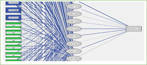
Figure 21. Architecture of artificial neural networks. The formal neurons are drawn as rectangles in blue and green (input), the weights (w) are represented by gray and blue lines connecting the layers of neurons. The fan-shaped neurons are drawn in white units, sigmoidal in gray ellipses (Hidden), and linear units in gray rectangles (output).
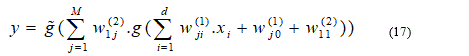
with the error function  . In this paper,
  is a linear function and g is a tan-sigmoid transfer function.
The learning of the neural network is typically performed on gradient descent-based algorithm variants, [63] attempting to minimize an error function. To avoid overloading cross validation can be used to find a training point earlier. In this work, the SPSS neural network toolbox was used [64]. The data were pre-processed identically to SVM-based learning. We applied the following training algorithms to ANN optimization in their default versions provided by MATLAB: gradient descent with variable learning rate, conjugate gradient descent, conjugate gradient descent, quasi-Newton algorithm, [65, 66] Levenberg-Marquardt (LM), [67] and automated regularization. For each optimization ten times cross-validation was performed (80 + 20 splits in training and test data), where the weights and biases of RNA were optimized using the training data, and the prediction accuracy was measured using test data to determine the number of training periods, i.e., the end point of the training process. training. This has been done to reduce the risk of over-learning. It should be noted that the validation data have not been affected (Table 4,5).
Table 5. Summary of the model
Training |
Sum of Squares Error |
5,339 |
Average Overall Relative Error |
0,076 |
Relative Error for Scale Dependents |
CDRV |
0,108 |
CDRH |
0,079 |
AreaRatio |
0,040 |
Stopping Rule Used |
1 consecutive step(s) with no decrease in errora |
Training Time |
00:00:01,026 |
Testing |
Sum of Squares Error |
0,003 |
Average Overall Relative Error |
. |
Relative Error for Scale Dependents |
CDRV |
b |
CDRH |
b |
AreaRatio |
b |
a. Error computations are based on the testing sample.
b. Cannot be computed. The dependent variable may be constant in the testing sample.
Predicting target values of test data by the SKVMs model
A classification task usually involves separating the data into training and test sets. Each instance of the training set contains a target value (i.e., class labels) and several attributes (i.e., observed characteristics or variables).
We used a vector support machine classifier (SVM), a supervised learning model, to classify the normal eye fundus from a fundus affected by glaucoma. The purpose of SVM is to produce a model (based on the learning data) that predicts the target values of the test data by giving only the attributes of the test data [68]. In our case, modified input image attribute sets after applying pre-processing techniques in the previous steps serve as test data.
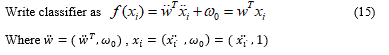
More formally, the linear SVM classifier function can be defined as, f (x) = wTx + b so that for each learning sample xi the function gives f (xi)> 0 for yi = +1, and f (xi) <0 for yi = -1. In other words, the learning samples of two different classes are separated by the hyperplane f (x) = wTx + b = 0, where w is vector of weight and normal to hyperplane, b is skew or threshold and xi is the data point.
The nonlinear SVM classifier is defined as: 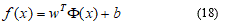
The transformation of a non-linear separation hyperplane into a linear one in a larger feature space is done using the functions of the kernel. A two-sample kernel function, represented as feature vectors in an input space, is defined by:
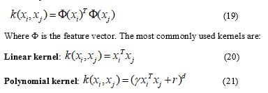
Where r is a free parameter exchanging the influence of the higher order and lower order terms in the polynomial, d is the degree of the polynomial, slope γ > 0.
Radial basis function (RBF) kernel K: 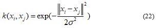
Where σ > 0 is an adjustable free parameter; a high value of σ means that the kernel is a “flattened” Gaussian and that the decision limit is “smoother”; a low value of σ makes the Gaussian kernel a “sharper” peak, and so the decision limit is more flexible.
A major advantage of the SVM classification is that SVM works well on datasets that have many attributes, even when there are only a few cases that are available for the training process. However, several disadvantages of the SVM classification include speed and size limitations during the training and testing phase of the algorithm and the selection of kernel function parameters.
A limitation of our study was the small sample size. This may affect the results when using the nine Gdx or SLO print data parameters. As mentioned earlier, complex machine classifiers that use many input parameters tend to work better in larger datasets. A more in-depth survey with a larger number of participants is currently underway.
In summary, machine classifiers of Gdx measurements can provide a simple and accurate index for diagnosing the presence or absence of glaucoma as well as its severity. Classifiers who used a limited number of parameters gave the best ability to discriminate. A classification system for the severity of glaucoma has been developed. A long-term prospective study is needed to determine the utility of this classification index in evaluating glaucoma progression, relative to existing parameters.
Contours Fitting for Optic Disc and Optic Cup
The active contours Chan & Vese algorithm can be used to find the fitting contours to disc and cup boundary.
Following the separation of the two parts of the Cup and the disc (Figure 22-27), would be asked to calculate the ratio of the Cup / Disc in terms of surface and vertically and horizontally with reference to the centroids.
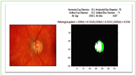
Figure 22. Values of CDRAutomated and AreaCup and others features extracted.
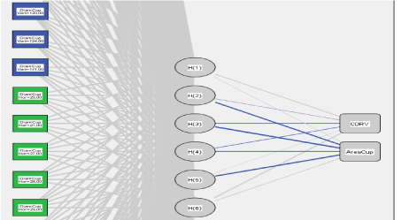
Figure 23. SVM Architecture. The support vectors are drawn as blue and green rectangles (input), the weights (w) are represented by grey and blue lines connecting the support vector layers. range vectors are drawn in white units, sigmoidal in grey ellipses (Hidden), and linear units in grey rectangles (output).
— synaptic weight> 0
— synaptic weight< 0
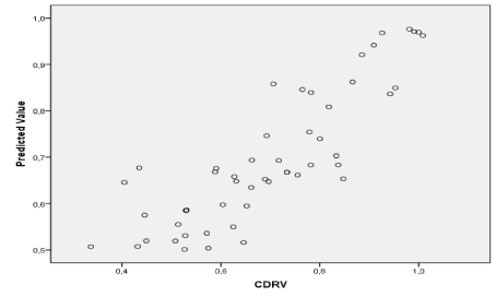
Figure 24. Prediction of glaucoma classes by the SVM technique using CDRV as support vectors.
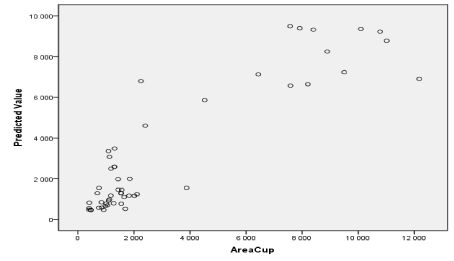
Figure 25. Prediction of glaucoma classes by the SVM technique using the cup area as support vectors.
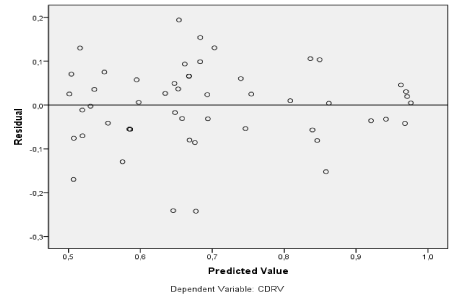
Figure 26. Prediction of glaucomatous cases (above the black line) using CDRv as a dependent variable.
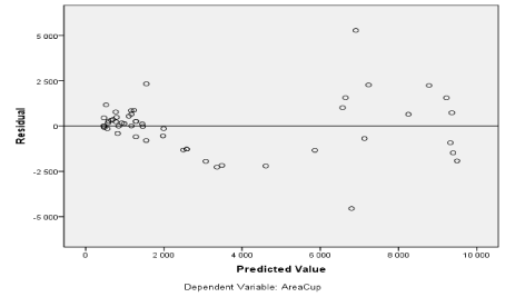
Figure 27. Prediction of glaucomatous cases (above the black line) using the cup area as a dependent variable.
Figure also shows other parameters be automatically extracted as the area of the excavation, which has evolved over time, helps the ophthalmologist specify the severity of retinal disease (Figure 22).
Since CDR is an important indicator used for glaucoma detection, this metric is chosen to evaluate our results. The CDRs (vertical & horizontal) are computed from the obtained cup and disc diameter from the chosen method.
Primary SKVMs Results
If the data is linearly separable, then the algorithm will converge.
- Convergence can be slow.
- Separating line close to training data.
- We would prefer a larger margin for generalization.
For the best of w, we can choose the maximum margin of solution that is most stable under perturbations of the inputs [69-72].
Figure 28 displays three categories of eyes: A suspect glaucomatous subjects with vectors xi neighbouring the hyperplan, healthy eyes with a group of vectors situated in the left (away) the hyperplan and finally, a group of vectors xi with a high value of CDR (Near to 1) represents a glaucomatous eye situated on the right of the hyperplan (True positive TP).
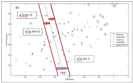
Figure 28. Classification (Glaucomatous from healthy eyes) performance of the two-feature extraction approaches, the hyperplan crosses through the means values of CDRV and the CDRH.
The classification performance using each feature extraction method separately shows that the accuracy varies between 65% and 95% in cross-validation. In addition, each feature extraction method itself has varying classification accuracy and F-measures for the different classifier configurations [73, 74]. The SKVMS separates the features most robustly and is always part of configurations labelled with the “finest”-criterion. The configurations with “finest”-criterion achieve CDR-measures between 0.30 and 0.50 for healthy case and between 0.53 and 0.99 for glaucomatous case in case of cross-validation. They are always using SVM for classification.
In case of the feature merging, the highest success rate and CDR-measures are obtained if a feature selection is done before using the SVM in case of cross-validation. In 2-stage classification, the class-probabilities of the “best”-labelled classifier configurations are used as second stage features.
As stated in SKVMs, results observers achieve an average CDRglau = 0.59 and CDRheal = 0.35 by qualitative assessment of optic nerve head stereo-photographs (25 healthy and 40 glaucomatous subjects). Regarding classification on separate test and training set, we gain a slightly inferior performance (CDRglau = 0.77) while we get CDRhealthy = 0.32 for healthy eye [75, 76].
One of the contributions of this paper is to show that sparing kernel combinations can be learnt in a tractable way using Support Kernel Vector Machines to distinguish normal eyes from those with glaucoma [77]. Consider, for example, the learnt patterns of finely for problems like the ones in figure 27 corresponding to recognition results in figure 21. Solutions of this form – a set of different kernels for each problem, but with good overall classification accuracy – are not easy to obtain using any of the algorithms currently used in object recognition. An SKVMs necessary method faces a combinatorial problem and no simple kernel enumeration technique can solve it optimally. It is not surprising that learning kernels produces competitive state-of-the art classifiers, neither that a rare combination may sometimes marginally hurt performance – this is a small price to pay for the benefit of compactness and selection. SKVMs provide a scalable solution for combining large numbers of kernels with heterogeneous feature spaces, where a-priori weighting intuitions may no longer be available [78].
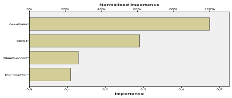
Figure 29. Illustration of the importance of the excavation area by contribution of other attributes to screen for glaucoma.
80 images are used for the training and 10 images are used for the tests each time. This process is repeated 10 times using different sessions of the test data each time. The performance of the classifier can be tested and evaluated by the following parameters:
- Accuracy rate = Correctly classified samples / Classified samples.
- Sensitivity = Correctly classified positive samples / Actual positive samples.
- Specificity = Correctly categorized negative samples / Real negative samples.
- Positive predictive precision = Correctly classified positive samples / Positive classified samples.
- Negative Predictive Accuracy = Correctly Classified Negative Samples / Negative Classified Samples.
Here, the sample designates the input images used for learning the classifier.
In this paper, after cross-validation, the trained SVM classifier gives an accuracy rate of 97%, a sensitivity of 99%, a specificity of 90%, a positive predictive accuracy of 94% and a negative predictive accuracy of 99.9. %.
After the training, we tested the trained classifier's performance on 75 fundus images (25 healthy and 40 affected glaucoma) that were not part of the set of input images. The SVM classifier can successfully classify this test with an accuracy rate of 93%, a sensitivity of nearly 100%, a specificity of 66%, a positive predictive accuracy of 89.28% and a negative predictive accuracy of almost 100%.
The methods used in references [79-82] are designated as method 1, method 2. Our method is called SVM.
We can observe that our SVM method is optimal compared to the other recent methods as regards the number of images and also the precision.
We used more images for classification and testing than methods 1 and 2 (Table 6-10).
Table 6. Comparison of training accuracy by different methods.
Method |
Technique used |
Number of images used / Method |
Training accuracy |
Method 1 |
Min-MaxNeural Fuzzy |
39 |
97% |
Method 2 |
Réseau neuronal artificiel |
40 |
85% |
SVM |
Support Vector Machine |
64 |
98% |
Table 7. Network information
Input Layer |
Factors |
1 |
DiamCupVert |
2 |
DiamCupHor |
Covariates |
1 |
CDRH |
2 |
AreaRatio |
Number of Units |
68 |
Rescaling Method for Covariates |
Adjusted normalized |
Hidden Layer |
Number of Units |
6a |
Activation Function |
Softmax |
Output Layer |
Dependent Variables |
1 |
CDRV |
2 |
AreaCup |
Number of Units |
2 |
Rescaling Method for Scale Dependents |
Adjusted normalized |
Activation Function |
Identity |
Error Function |
Sum of Squares |
- Determined by test data criteria: The "best" number of hidden units is the one that generates the smallest error in the test data.
Table 8. Summary of the Radial Basis Function RBF model.
Training |
Sum of Squares Error |
3,324 |
Average Overall Relative Error |
0,227 |
Relative Error for Scale Dependents |
CDRV |
0,285 |
AreaCup |
0,185 |
Training Time |
00:00:00,644 |
Testing |
Sum of Squares Error |
0,100a |
Average Overall Relative Error |
0,429 |
Relative Error for Scale Dependents |
CDRV |
0,302 |
AreaCup |
2,602 |
- The number of hidden units is determined by the test data criterion: The "best" number of hidden units is the one that produces the smallest error in the test data.
Table 9. Estimations of parameters
Predictor |
Predicted |
Hidden Layera |
Output Layer |
H(1) |
H(2) |
H(3) |
H(4) |
H(5) |
H(6) |
CDRV |
AreaCup |
Input Layer |
[DiamCupVert=20,00] |
0,000 |
0,000 |
0,100 |
0,000 |
0,000 |
0,000 |
|
|
[DiamCupVert=22,00] |
0,000 |
0,000 |
0,100 |
0,000 |
0,000 |
0,000 |
|
|
[DiamCupVert=27,00] |
0,000 |
0,000 |
0,100 |
0,000 |
0,000 |
0,000 |
|
|
[DiamCupVert=30,00] |
0,000 |
0,000 |
0,100 |
0,000 |
0,000 |
0,000 |
|
|
[DiamCupVert=31,00] |
0,000 |
0,000 |
0,200 |
0,000 |
0,000 |
0,000 |
|
|
[DiamCupVert=32,00] |
0,000 |
0,000 |
0,100 |
0,000 |
0,000 |
0,000 |
|
|
[DiamCupVert=33,00] |
0,000 |
0,000 |
0,100 |
0,000 |
0,000 |
0,000 |
|
|
[DiamCupVert=36,00] |
0,000 |
0,000 |
0,000 |
0,000 |
0,500 |
0,000 |
|
|
[DiamCupVert=37,00] |
0,000 |
0,250 |
0,000 |
0,000 |
0,000 |
0,000 |
|
|
[DiamCupVert=38,00] |
0,000 |
0,000 |
0,100 |
0,000 |
0,000 |
0,000 |
|
|
[DiamCupVert=39,00] |
0,000 |
0,000 |
0,000 |
0,000 |
0,250 |
0,000 |
|
|
[DiamCupVert=40,00] |
0,000 |
0,250 |
0,000 |
0,000 |
0,000 |
0,000 |
|
|
[DiamCupVert=41,00] |
0,000 |
0,000 |
0,100 |
0,000 |
0,000 |
0,000 |
|
|
[DiamCupVert=43,00] |
0,000 |
0,000 |
0,000 |
0,000 |
0,250 |
0,000 |
|
|
[DiamCupVert=44,00] |
0,000 |
0,000 |
0,000 |
0,286 |
0,000 |
0,000 |
|
|
[DiamCupVert=45,00] |
0,000 |
0,000 |
0,000 |
0,571 |
0,000 |
0,000 |
|
|
[DiamCupVert=50,00] |
0,000 |
0,250 |
0,000 |
0,000 |
0,000 |
0,000 |
|
|
[DiamCupVert=51,00] |
0,000 |
0,250 |
0,000 |
0,000 |
0,000 |
0,000 |
|
|
[DiamCupVert=52,00] |
0,125 |
0,000 |
0,000 |
0,000 |
0,000 |
0,000 |
|
|
[DiamCupVert=54,00] |
0,000 |
0,000 |
0,000 |
0,143 |
0,000 |
0,000 |
|
|
[DiamCupVert=67,00] |
0,125 |
0,000 |
0,000 |
0,000 |
0,000 |
0,000 |
|
|
[DiamCupVert=72,00] |
0,125 |
0,000 |
0,000 |
0,000 |
0,000 |
0,000 |
|
|
[DiamCupVert=81,00] |
0,125 |
0,000 |
0,000 |
0,000 |
0,000 |
0,000 |
|
|
[DiamCupVert=97,00] |
0,125 |
0,000 |
0,000 |
0,000 |
0,000 |
0,000 |
|
|
[DiamCupVert=100,00] |
0,000 |
0,000 |
0,000 |
0,000 |
0,000 |
0,429 |
|
|
[DiamCupVert=105,00] |
0,000 |
0,000 |
0,000 |
0,000 |
0,000 |
0,143 |
|
|
[DiamCupVert=110,00] |
0,125 |
0,000 |
0,000 |
0,000 |
0,000 |
0,000 |
|
|
[DiamCupVert=114,00] |
0,125 |
0,000 |
0,000 |
0,000 |
0,000 |
0,000 |
|
|
[DiamCupVert=115,00] |
0,000 |
0,000 |
0,000 |
0,000 |
0,000 |
0,143 |
|
|
[DiamCupVert=120,00] |
0,000 |
0,000 |
0,000 |
0,000 |
0,000 |
0,143 |
|
|
[DiamCupVert=124,00] |
0,000 |
0,000 |
0,000 |
0,000 |
0,000 |
0,143 |
|
|
[DiamCupVert=141,00] |
0,125 |
0,000 |
0,000 |
0,000 |
0,000 |
0,000 |
|
|
[DiamCupHor=20,00] |
0,000 |
0,000 |
0,300 |
0,000 |
0,000 |
0,000 |
|
|
[DiamCupHor=21,00] |
0,000 |
0,000 |
0,100 |
0,000 |
0,000 |
0,000 |
|
|
[DiamCupHor=27,00] |
0,000 |
0,000 |
0,000 |
0,000 |
0,125 |
0,000 |
|
|
[DiamCupHor=28,00] |
0,000 |
0,000 |
0,000 |
0,000 |
0,125 |
0,000 |
|
|
[DiamCupHor=29,00] |
0,000 |
0,000 |
0,200 |
0,143 |
0,000 |
0,000 |
|
|
[DiamCupHor=30,00] |
0,000 |
0,000 |
0,100 |
0,000 |
0,000 |
0,000 |
|
|
[DiamCupHor=31,00] |
0,000 |
0,000 |
0,000 |
0,000 |
0,250 |
0,000 |
|
|
[DiamCupHor=32,00] |
0,000 |
0,125 |
0,000 |
0,000 |
0,000 |
0,000 |
|
|
[DiamCupHor=33,00] |
0,000 |
0,000 |
0,000 |
0,000 |
0,125 |
0,000 |
|
|
[DiamCupHor=34,00] |
0,000 |
0,125 |
0,000 |
0,000 |
0,000 |
0,000 |
|
|
[DiamCupHor=36,00] |
0,000 |
0,000 |
0,000 |
0,000 |
0,125 |
0,000 |
|
|
[DiamCupHor=37,00] |
0,000 |
0,000 |
0,200 |
0,000 |
0,000 |
0,000 |
|
|
[DiamCupHor=38,00] |
0,000 |
0,250 |
0,000 |
0,000 |
0,000 |
0,000 |
|
|
[DiamCupHor=40,00] |
0,000 |
0,000 |
0,000 |
0,143 |
0,125 |
0,000 |
|
|
[DiamCupHor=42,00] |
0,125 |
0,000 |
0,000 |
0,000 |
0,000 |
0,000 |
|
|
[DiamCupHor=43,00] |
0,000 |
0,125 |
0,000 |
0,000 |
0,000 |
0,000 |
|
|
[DiamCupHor=44,00] |
0,000 |
0,125 |
0,000 |
0,000 |
0,000 |
0,000 |
|
|
[DiamCupHor=45,00] |
0,000 |
0,000 |
0,000 |
0,143 |
0,000 |
0,000 |
|
|
[DiamCupHor=46,00] |
0,000 |
0,000 |
0,000 |
0,429 |
0,000 |
0,000 |
|
|
[DiamCupHor=47,00] |
0,000 |
0,000 |
0,000 |
0,143 |
0,000 |
0,000 |
|
|
[DiamCupHor=49,00] |
0,000 |
0,125 |
0,000 |
0,000 |
0,000 |
0,000 |
|
|
[DiamCupHor=59,00] |
0,125 |
0,000 |
0,000 |
0,000 |
0,000 |
0,000 |
|
|
[DiamCupHor=60,00] |
0,000 |
0,125 |
0,000 |
0,000 |
0,000 |
0,000 |
|
|
[DiamCupHor=62,00] |
0,125 |
0,000 |
0,000 |
0,000 |
0,000 |
0,000 |
|
|
[DiamCupHor=80,00] |
0,000 |
0,125 |
0,000 |
0,000 |
0,000 |
0,000 |
|
|
[DiamCupHor=85,00] |
0,125 |
0,000 |
0,000 |
0,000 |
0,000 |
0,000 |
|
|
[DiamCupHor=89,00] |
0,125 |
0,000 |
0,000 |
0,000 |
0,000 |
0,000 |
|
|
[DiamCupHor=91,00] |
0,000 |
0,000 |
0,000 |
0,000 |
0,000 |
0,286 |
|
|
[DiamCupHor=96,00] |
0,125 |
0,000 |
0,000 |
0,000 |
0,000 |
0,000 |
|
|
[DiamCupHor=99,00] |
0,125 |
0,000 |
0,000 |
0,000 |
0,000 |
0,000 |
|
|
[DiamCupHor=102,00] |
0,000 |
0,000 |
0,000 |
0,000 |
0,000 |
0,286 |
|
|
[DiamCupHor=105,00] |
0,000 |
0,000 |
0,000 |
0,000 |
0,000 |
0,143 |
|
|
[DiamCupHor=110,00] |
0,000 |
0,000 |
0,000 |
0,000 |
0,000 |
0,286 |
|
|
[DiamCupHor=117,00] |
0,125 |
0,000 |
0,000 |
0,000 |
0,000 |
0,000 |
|
|
CDRH |
0,308 |
0,165 |
0,378 |
0,182 |
0,229 |
0,773 |
|
|
AreaRatio |
0,231 |
0,256 |
0,630 |
0,444 |
0,272 |
0,772 |
|
|
Hidden Unit Width |
0,467 |
0,441 |
0,467 |
0,424 |
,439 |
0 ,432 |
|
|
Hidden Layer |
H(1) |
|
|
|
|
|
|
0,559 |
0,164 |
H(2) |
|
|
|
|
|
|
-0,048 |
-0,981 |
H(3) |
|
|
|
|
|
|
-0,518 |
-0,992 |
H(4) |
|
|
|
|
|
|
-0,249 |
-0,837 |
H(5) |
|
|
|
|
|
|
0,050 |
-0,985 |
H(6) |
|
|
|
|
|
|
0,910 |
0,549 |
- Displays the central vector for each hidden unit.
Table 10. Importance of each independent variable
|
Importance |
Normalized importance |
DiamCupVert |
0,129 |
27,2% |
DiamCupHor |
0,108 |
22,9% |
CDRH |
0,289 |
61,1% |
AreaRatio |
0,474 |
100,0% |
Predicted by the observed graphs
Shown in
Residual by provided graphics
Shown in
Descriptive statistics to examine features extracted to distinguish glaucomatous from healthy subjects
t-test and chi-square test
Data were presented as means (standard deviation) for continuous variables and as proportions for categorical variables. Comparison of continuous variables between groups (CDRv and CDRH) was made with independent Student's t-test. For discrete variables, distribution between groups was compared with Chi-square test as appropriate (where an expected cell is <5). Cup diameter (V&H) – Disc diameter (V&H) related differences in the occurrence of excavation among patients with glaucoma disease were evaluated using Chi-square for drift. All statistical analyses were carried out using the Statistical Packages for Social Sciences (SPSS Inc., Chicago Illinois, USA) software version 16.0. Statistical tests with two-tailed p < 0.05 were considered statistically significant.
A Paired sample t-test compares means from the same group at different axis, as shown in Table 11,12.
Table 11. Paired Samples Statistics
|
|
Mean |
N |
Std.deviation |
Std.error |
Pair 1 |
CDRV
CDRH |
0,6995
0,6908 |
64
64 |
0,17631
0,15887 |
0,02204
0,01986 |
Pair 2 |
Area Cup
Area Disc |
3448
5495 |
64
64 |
3650,51
4143,55 |
456,31
517,94 |
Pair 3 |
Diam.CupV
Diam.DiscV |
58,5313
80,1094 |
64
64 |
33,56
30,45 |
4,19443
3,80653 |
Pair 4 |
Diam.CupH
Diam.DiscH |
54,9063
75,8750 |
64
64 |
30,98
30,88 |
3,87213
3,85974 |
Table 12. Chi-square Test Statistics for CDRV & CDRH
|
CDRV |
CDRH |
Chi-square |
1,875a |
7,906b |
df |
61 |
58 |
Asymp. Sig. |
1,000 |
1,000 |
a. 62 cells (100,0%) have expected frequencies less than 5. The minimum expected cell frequency is 1,0.
b. 59 cells (100,0%) have expected frequencies less than 5. The minimum expected cell frequency is 1,1.
The null hypothesis for the independent samples t-test is:
μ1(0,6995) = μ2(0,6908). In other words, it assumes the means are equal. With the paired t test, the null hypothesis is that the pairwise difference between the two tests is equal (H0: µd = 0). The difference between the two tests is very subtle (0,00877); which one you choose is based on the data collection method.
The following formula is used to calculate the t-score:
Where: ∑D is the sum of the differences (Sum of X-Y, CDRV - CDRH)
∑D2: Sum of the squared differences.
(∑D)2: Sum of the differences squared
t = 0,529
The degrees of freedom df = 64-1 = 63
Every t-value has a p-value (p = 0.05, level confidence is 95%) to go with it. A p-value is the probability that the results from the sample data occurred by chance. The p-value in the t-table, using the degrees of freedom for this sample problem, with df=63, the t-value is 2,000.
The calculated t-value is smaller than the table value at an alpha level of 0.05. The p-value is less than the alpha level: p <0.05. We can reject the null hypothesis that there is no difference between means (Table 12-14).
Table 13. Paired Samples Test
|
Paired Différences |
t |
df |
Sig.
(2-tailed) |
Mean |
Std. Deviation |
Std. Error Mean |
95% Confidence Interval of the Difference |
Lower |
Upper |
Pair1 |
CDRV - CDRH |
0,009 |
0,13 |
0,017 |
-0,02436 |
0,042 |
0,53 |
63 |
0,6 |
Pair2 |
Area (Cup – Disc) |
-2047 |
1294 |
161,754 |
-2370,33 |
-1724 |
-12,66 |
63 |
0,0 |
Pair3 |
Diam(Cup-Disc)v |
-21,58 |
14,40 |
1,80000 |
-25,17 |
-17,98 |
-11,99 |
63 |
0,0 |
Pair4 |
Diam(Cup-Disc)H |
-20,97 |
11,04 |
1,37959 |
-23,7256 |
-18,21 |
-15,2 |
63 |
0,0 |
Table 14. Chi-squareTest Statistics for the others features
|
AreaCup |
AreaDisc |
DiamCupVert |
DiamDiscVert |
DiamCupHor |
DiamDiscHor |
Chi-square |
1,875a |
1,875a |
20,656b |
12,188c |
17,375d |
18,250e |
df |
61 |
61 |
42 |
45 |
41 |
46 |
Asymp. Sig. |
1,000 |
1,000 |
0,998 |
1,000 |
1,000 |
1,000 |
a. 62 cells (100,0%) have expected frequencies less than 5. The minimum expected cell frequency is 1,0.
|
b. 43 cells (100,0%) have expected frequencies less than 5. The minimum expected cell frequency is 1,5.
|
c. 46 cells (100,0%) have expected frequencies less than 5. The minimum expected cell frequency is 1,4.
|
d. 42 cells (100,0%) have expected frequencies less than 5. The minimum expected cell frequency is 1,5.
|
e. 47 cells (100,0%) have expected frequencies less than 5. The minimum expected cell frequency is 1,4. |
The percentile plots
There are a couple of reasons for preferring percentile plots to cumulative fractions plots. It turns out that the percentile plot is a better estimate of the distribution function (if you know what that is). In addition, plotting percentiles allows you to use “probability graph paper” plots with specially scaled axis divisions. Probability scales on the y-axis allows you to see how “normal” the data is. Normally distributed data will plot as a straight line on probability paper. Lognormal data will plot as a straight line with probability-log scaled axes. (Incidentally, uniformly distributed data will plot as a straight line using the usual linear y-scale) (Table 15).
Table 15. Estimated Distribution Parameters
|
CDRV |
CDRH |
Lognormal Distribution |
Scale |
0,676 |
0,672 |
Shape |
0,271 |
0,243 |
The cases are unweighted.
The KS-test
The KS-test reported the CDRV data (treatment A) in the second example was approximately lognormal with geometric mean of 0,6995 and multiplicative standard deviation of 0,17631. In the below plot, I display the percentile plot of this data (in red) along with the performance expected for the above lognormal distribution (in blue).
Note that the KS-test reports that both treatment B and control B data are approximately lognormal. Thus, you could take the log of all the data, and use the resulting data in a t-test. Since the t-test is a quite sensitive test when applied to appropriate data this would be the best strategy.
Similar consideration of the CDRH data (treatment B) in the first example lead to the following plot. Here the KS-test reported that the data was approximately normally distributed with mean = 0,6908 and standard deviation = 0,15887 (Figure 30).
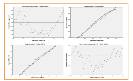
Figure 30. Schemes to cumulative fractions plots.
These datasets were drawn from lognormal distributions that differ substantially in mean. The KS test detects this difference; the t-test does not. Of course, if we knew that, the data were non-normally distributed; we would know not to apply the t-test in the first place.
One of the advantages of the KS-test is that it leads to a graphical presentation of the data, which enables the user to detect normal distributions (see below). For larger datasets (say N>40), the Central Limit Theorem suggests that the t-test will produce valid results even in the face of non-normally distributed data. However, highly non-normal datasets can cause the t-test to produce fallible results, even for large N datasets. In the last example you will see a case where the t-test fails at N=80 (Figure 31) (Table 16).
Table 16. One-Sample Kolmogorov-Smirnov Test
|
CDRV |
CDRH |
N |
64 |
64 |
Normal Parametersa,b |
Mean |
0,6995 |
0,6908 |
Std. Deviation |
0,17631 |
0,15887 |
Most Extreme Differences |
Absolute |
0,066 |
0,051 |
Positive |
0,066 |
0,046 |
Negative |
-0,062 |
-0,051 |
Kolmogorov-Smirnov Z |
0,529 |
0,412 |
Asymp. Sig. (2-tailed) |
0,943 |
0,996 |
a. Test distribution is Normal.
b. Calculated from data.
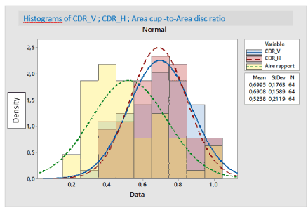
Figure 31. "Histograms with a normal distribution: Diameter vertical cup DiamCupHorizontal and area of the excavation" - MAPPING ("x" = "DiamCupVert") (Excavation along the vertical axis).
These distributions as well as all other normal distributions are symmetrical with relatively more values in the center of the distribution and relatively fewer in the extremities.
The Kolmogorov-Smirnov test (KS-test) tries to determine if two datasets (CDRV & CDRH) differ significantly. The KS-test has the advantage of making no assumption about the distribution of data. (Technically speaking it is non-parametric and distribution free.) Note however, that this generality comes at some cost: other tests (for example Student's t-test) may be more sensitive if the data meet the requirements of the test. In addition to calculating the D statistic, this result will report if the data seem normal or lognormal. (If it is silent, assume normal data) It will enable to view the data graphically which can help to understand how the data is distributed.
Using 75 images obtained from a clinical case of a glaucomatous subjects, the performance of our approach is evaluated using the proximity of the calculated CDR to the manually graded CDR. The results indicate that our approach provides 98% accuracy in glaucoma analysis. As a result, this study has a good potential in automated screening systems for the early detection of glaucoma.
;We presented a novel automated glaucoma classification system using digital fundus images. In contrast to the commonly used segmentation based measurements, it is purely data-driven and uses image-based features that are new in the domain of glaucoma recognition. We evaluated several combinations of image-based features and classifier schemes on a set of 75 real fundus images. The 2-stage classification with SKVMs produced 96% success rate. The performance of the fully automatic system presented here is comparable to medical experts in detecting glaucomatous eyes and it could be used in mass-screenings. The important features automatically identified by the methods also provide a novel representation of the data for the physicians and may help to enhanced understand glaucoma disease.
Glaucoma is an eye disease that can cause blindness if it is not detected and treated at the right time. The increase in intraocular pressure (IOP) of the fluid in the eye often causes glaucoma. Glaucoma is the second leading cause of blindness in the world and is called the “silent thief of sight”.
Optical coherence tomography (OCT) and Heidelberg retinal tomography (HRT) techniques for the detection of glaucoma are very expensive. A method to diagnose glaucoma using digital images of the fundus is presented in this paper. The purpose of our proposed method is to apply image processing techniques to the fundus digital images for the analysis of the glaucomatous eye and the healthy eye. Image pre-processing techniques such as noise suppression and contrast enhancement, Hough Circular Transformation (CHT) method and Chan-Vese model active contours for feature extraction and attributes to identify glaucoma pathology and SVM (Support Vector Machine) method for image classification are used in the proposed method. All of these techniques are implemented via MATLAB and C # which offers a variety of options for image processing that allow us to extract the required features and information from the images.
Nevertheless, our results indicate that solutions obtained through SVM training appear to be more robust with a smaller standard error compared to standard ANN training. Regardless of the outcome of this study, it is the appropriate choice of learning data and descriptors, and reasonable scaling of the input variables determines the success or failure of machine learning system. Both methods are suitable for evaluating the utility of different sets of descriptors for a given classification task, and they are methods of choice for rapid first-pass filtering of compounds in the dataset. A particular advantage of SVM is “dispersion of the solution”. This means that an SVM classifier depends only on the support vectors, and the classifier function is not influenced by all the data, as is the case for many neural network systems. Another enhancement of SVM is the ability to deal effectively with a very large number of features due to the exploitation of kernel functions, making it an attractive technique. The combination of SVM with a selection of routine features could provide an effective tool for digitally extracting relevant information.
I wish to express my sincere gratitude to Professors Imed and Hédi for their assistance in the preparation of this manuscript. I would like to express my thanks to Mr. Imed Jabri, my research director for his admirable generosity, his advice, his tips, his availability, his tolerance and his support throughout these years. With insight, he knew how to choose the most rewarding ways.
May he find here the expression of my deep gratitude and admiration.
I would also like to thank the professors Mrs Ines Taamallah Malek for the course of understanding of glaucoma as pathology, Mr Hédi Trabelsi for the course of optics used in ophthalmology and the financial aids via research grants or training and Mr Imed Jabri for the numerical approaches modelling course used to detect the disc and excavation of the optic nerve head.
I could not conclude without quoting and thanking Mrs. Hlima Mahjoubi and all the professors who taught me or train me during this research process, researchers at the biophysics laboratory who have been witnesses of my learning of the research and development system. Other biophysical themes that we had together, as well as for their help in putting my first steps into the field of research and imaging.
My thanks also go to all the members of the Latice and Lrbtm laboratory and to all the staff of the Department of Biophysics and Scientific Research.
Author’s contributions
I.J., I.M. and R.B conceived and designed the experiments; I.J. and R.B. performed the experiments; I.M., R.B and I.J. analysed the data; H.T., I.J. and R.B contributed reagents/ materials/ analysis tools; R.B. wrote the paper; H.T., R.B., I.M and I.J. discussed and proof-read the manuscript.
Ethics approval and consent to participate
Written informed consent was obtained from the patients for publication of this manuscript and any accompanying images.
This work is supported in part by 1 Laboratory of Research in Biophysics and Medical Technologies LRBTM Higher Institute of Medical Technologies of Tunis ISTMT; University of Tunis El Manar Address: 9, Rue Dr Zouheïr Safi _1006.
And in additional part by 2 Higher National School of engineering of Tunis, ENSIT, Laboratory LATICE (Information Technology and Communication and Electrical Engineering LR11ESO4), University of Tunis EL Manar.
- Zangwill LM1, Chan K, Bowd C, Hao J, Lee TW, et al. (2004) Heidelberg retina tomograph measurements of the optic disc and parapapillary retina for detecting glaucoma analyzed by machine learning classifiers. Invest Ophthalmol Vis Sci 45: 3144–3151[Crossref]
- Meier J, Bock R, Michelson G, Ny´ul LG, Hornegger J (2007) Effects of preprocessing eye fundus images on appearance-based glaucoma classification. In: Procceedings of International Conference on Computer Analysis of Images and Patterns.
- Lester M, Garway-Heath D, Lemij H (2005) Optic Nerve Head and Retinal Nerve Fibre Analysis. European Glaucoma Society
- Jain A, Farrokhnia F (1990) Unsupervised texture segmentation using Gabor filters.In: Proceedings of IEEE International Conference on Systems, Man and Cybernetics. 14–19
- Freund Y, Schapire RE (1996) Experiments with a new boosting algorithm. In: Proceedings of the Thirteenth International Conference on Machine Learning. 148–156
- Bach FR, Lanckriet GRG, Jordan MI (2004) Multiple kernel learning, conic duality, and the SMO algorithm. In ICML, New York, USA.
- Heijl A, Buchholz P, Norrgren G, Bengtsson B (2013) Rates of visual field progression in clinical glaucoma care. Acta Ophthalmol 91: 406-412. [Crossref]
- Kass MA, Heuer DK, Higginbotham EJ, Johnson CA, Keltner JL, et al. (2002) The Ocular Hypertension Treatment Study: a randomized trial determines that topical ocular hypotensive medication delays or prevents the onset of primary open-angle glaucoma. Arch Ophthalmol 120: 701-713. [Crossref]
- Heijl A, Buchholz P, Norrgren G, Bengtsson B (2013) Rates of visual field progression in clinical glaucoma care. Acta Ophthalmol 91: 406-412. [Crossref]
- [Crossref] Broman AT, Quigley HA, West SK, Katz J, Munoz B, et al. (2008) Estimating the rate of progressive visual field damage in those with open-angle glaucoma, from cross-sectional data. Invest Ophthalmol Vis Sci 49: 66-76.
- Anusorn CB, Kongprawechnon W, Kondo T, Sintuwong S, Tungpimolrut K (2013) Image Processing Techniques for Glaucoma Detection Using the Cup-to-Disc Ratio.
- Wong D, Liu J, Lim J, Jia X, Yin F (2008) Wong, Level- set based automatic cup-to-disc ratio determination using retinal fundus images in ARGALI. Engineering in Medicine and Biology Society.2266-2269.
- Kavitha S, Karthikeyanand S. Duraiswamy (2010) Early Detection of Glaucoma in Retinal Images Using Cup to Disc Ratio, Computing Communication and Networking Technologies (ICCCNT) 1-5.
- Zhao HK, Chan T, Merriman B, Osher S (1996) A Variational Level Set Approach to Multiphase Motion. Journal of Computational Physics 127: 179-195.
- Zhao HK, Osher S, Merriman B, Kang M (1998) Implicit, Nonparametric Shape Reconstruction from Unorganized points using a variational Level Set Method. UCLA CAM Report 98-97.
- Crum WR, Camara O, Hill DL (2006) Generalized overlap measures for evaluation and validation in medical image analysis. IEEE Trans Med Imaging 25: 1451-1461. [Crossref]
- Cardoso JS, Corte-Real L (2005) Toward a generic evaluation of image segmentation. IEEE Trans Image Process 14: 1773-1782. [Crossref]
- Udupa J, LaBlanc V, Schmidt H, Imielinska C, Saha P (2002) A methodology for evaluating image segmentation algorithms. In: SPIE Conf. on Medical Imaging, San Diego, USA.
- Collins DL, Zijdenbos AP, Kollokian V, Sled JG, Kabani NJ, et al. (1998) Design and construction of a realistic digital brain phantom. IEEE Trans Med Imaging 17: 463-468. [Crossref]
- Vapnik V (1998) Statistical Learning Theory. New York: Wiley.
- Vapnik V (2000) The Nature of Statistical Learning Theory. 2. New York: Springer.
- Bowd C, Chan K, Zangwill LM, Goldbaum MH, Lee TW, et al. (2002) Comparing neural networks and linear discriminant functions for glaucoma detection using confocal scanning laser ophthalmoscopy of the optic disc. Invest Ophthalmol Vis Sci. 43: 3444–3454. [Crossref]
- Goldbaum MH, Sample PA, Chan K, Williams J, Lee TW, et al. (2002) Comparing machine learning classifiers for diagnosing glaucoma from standard automated perimetry. Invest Ophthalmol Vis Sci 43: 162–169. [Crossref]
- Bishop CM, Tipping ME (2000) Variational relevance vector machines. In: Boutilier C, Goldszmidt M, editors. Uncertainty in Artificial Intelligence. Cambridge, UK: Microsoft Research 45–63.
- Tipping ME (2001) Sparse Bayesian learning and the relevance vector machine. J Mach Learn Res 1: 211–244.
- Hodapp E, Parrish RK, Anderson DR (1993) Clinical Decisions in Glaucoma. St. Louis, MO: Mosby.
- Weinreb RN, Dreher AW, Coleman A, Quigley H, Shaw B, et al. (1990) Histopathologic validation of Fourier-ellipsometry measurements of retinal nerve fiber layer thickness. Arch Ophthalmol 108: 557–560. [Crossref]
- Bagga H, Greenfield DS (2004) Retinal nerve fiber layer assessment using scanning laser polarimetry. Int Ophthalmol Clin 44: 29-42. [Crossref]
- Zangwill LM, Medeiros FA, Bowd C, Weinreb RN (2004) Optic nerve imaging: recent advances. In: Grehn F, Stamper R, editors. Glaucoma. Berlin: Springer-Verlag 63–91.
- Christopher Bowd, Linda M. Zangwill, Felipe A. Medeiros, Jiucang Hao, Kwokleung Chan, et al. (2004) Confocal scanning laser ophthalmoscopy classifiers and stereophotograph evaluation for prediction of visual field abnormalities in glaucoma-suspect eyes. Invest Ophthalmol Vis Sci 45: 2255–2262. [Crossref]
- Strauss DJ, Delb W, Plinkert PK (2004) Objective detection of the central auditory processing disorder: a new machine learning approach. IEEE Trans Biomed Eng 51: 1147–1155.
- Shoeb A, Edwards H, Connolly J, Bourgeois B, Treves ST, et al. (2004) Patient-specific seizure onset detection. Epilepsy Behav 5: 483-498. [Crossref]
- Campanini R, Dongiovanni D, Iampieri E, Lanconelli N, Masotti M, et al. (2004) A novel featureless approach to mass detection in digital mammograms based on support vector machines. Phys Med Biol 49: 961–975. [Crossref]
- Weinreb RN, Bowd C, Greenfield DS, Zangwill LM (2002) Measurement of the magnitude and axis of corneal polarization with scanning laser polarimetry. Arch Ophthalmol 120: 901-906. [Crossref]
- Zhou Q, Weinreb RN (2002) Individualized compensation of anterior segment birefringence during scanning laser polarimetry. Invest Ophthalmol Vis Sci 43: 2221–2228. [Crossref]
- Sample PA, Goldbaum MH, Chan K, Boden C, Lee TW, et al. (2002) Using machine learning classifiers to identify glaucomatous change earlier in standard visual fields. Invest Ophthalmol Vis Sci 43: 2660–2665. [Crossref].
- Zangwill LM, Chan K, Bowd C, Hao J, Lee TW, et al. (2004) Heidelberg retina tomograph measurements of the optic disc and parapapillary retina for detecting glaucoma analyzed by machine learning classifiers. Invest Ophthalmol Vis Sci 45: 3144–3151. [Crossref]
- Christopher Bowd,Linda M. Zangwill, Felipe A. Medeiros, Jiucang Hao, Kwokleung Chan, et al. (2004) Confocal scanning laser ophthalmoscopy classifiers and stereophotograph evaluation for prediction of visual field abnormalities in glaucoma-suspect eyes. Invest Ophthalmol Vis Sci 45: 2255–2262. [Crossref]
- Strauss DJ, Delb W, Plinkert PK (2004) Objective detection of the central auditory processing disorder: a new machine learning approach. IEEE Trans Biomed Eng 51: 1147–1155.
- Shoeb A, Edwards H, Connolly J, Bourgeois B, Treves ST, et al. (2004) Patient-specific seizure onset detection. Epilepsy Behav 5: 483-498. [Crossref]
- Campanini R, Dongiovanni D, Iampieri E, Lanconelli N, Masotti M, et al. (2004) A novel featureless approach to mass detection in digital mammograms based on support vector machines. Phys Med Biol 49: 961-975. [Crossref]
- Piliouras N, Kalatzis I, Dimitropoulos N, Cavouras D (2004) Development of the cubic least squares mapping linear-kernel support vector machine classifier for improving the characterization of breast lesions on ultrasound. Comput Med Imaging Graph 28: 247–255. [Crossref]
- Bishop CM, Tipping ME (2003) Bayesian regression and classification. In: Suykens J, Horvath G, Basu S, Micchelli C, Vandewalle J, editors. Advances in Learning Theory: Methods, Models and Applications (NATO Science Series. Series III, Computer and Systems Sciences. 267–285.
- DeLong ER, DeLong DM, Clarke-Pearson DL (1988) Comparing the areas under two or more correlated receiver operating characteristic curves: a nonparametric approach. Biometrics 44: 837-845. [Crossref]
- Vese LA and Chan TF (2002) A Multiphase Level Set Framework for Image Segmentation Using the Mumford and Shah Model. Intl. J. of Comp.
- Zhao HK, Chan T, Merriman B, Osher S (1996) A Variational Level Set Approach to Multiphase Motion. Journal of Computational Physics 127: 179-195.
- Zhao HK, Osher S, Merriman B, Kang M Implicit (1998) Nonparametric Shape Reconstruction from Unorganized points using a variational Level Set Method. UCLA CAM Report 98.
- Iester M, Swindale NV, Mikelberg FS (1997) Sector-based analysis of optic nerve head shape parameters and visual field indices in healthy and glaucomatous eyes. J Glaucoma 6: 370–376.[Crossref]
- Zangwill LM, Chan K, Bowd C, Hao J, Lee TW, et al. (2004) Heidelberg retina tomograph measurements of the optic disc and parapapillary retina for detecting glaucoma analyzed by machine learning classifiers. Invest Ophthalmol Vis Sci 45: 3144–3151. [Crossref]
- Greaney MJ, Hoffman DC, Garway-Heath DF, Nakla M, Coleman AL, et al. (2002) Comparison of optic nerve imaging methods to distinguish normal eyes from those with glaucoma. Invest Ophthalmol Vis Sci 43: 140-145. [Crossref]
- Zhao W, Chellappa R, Phillips PJ, Rosenfeld (2003) A Face recognition: A literature survey. ACM Comput Surv 35: 399–458
- Meier J, Bock R, Michelson G, Ny´ul LG, Hornegger J (2007) Effects of preprocessing eye fundus images on appearance based glaucoma classification. In: Procceedings of International Conference on Computer Analysis of Images and Patterns.
- Lester M, Garway-Heath D, Lemij H(2005) Optic Nerve Head and Retinal Nerve Fibre Analysis. European Glaucoma Society.
- Jain A, Farrokhnia F (1990) Unsupervised texture segmentation using Gabor filters.In: Proceedings of IEEE International Conference on Systems, Man and Cybernetics. 14–19.
- John GH, Langley P (1995) Estimating continuous distributions in bayesian classifiers. In: Proceedings of the Eleventh Conference on Uncertainty in Artifical Intelligence, San Mateo, Morgan Kaufmann Publishers 338–345.
- Chen PH, Lin CJ, Sch¨olkopf B (2005) A tutorial on -support vector machines. Applied Stochastic Models in Business and Industry 21: 111–136
- Hall MA (1999) Correlation-based Feature Selection for Machine Learning. PhD thesis, University of Waikato, Hamilton, New Zealand.
- Freund Y, Schapire RE (1996) Experiments with a new boosting algorithm. In: Proceedings of the Thirteenth International Conference on Machine Learning. 148–156.
- Bach FR, Lanckriet, GRG, Jordan MI (2004) Multiple kernel learning, conic duality, and the SMO algorithm. In ICML, New York, USA.
- Bach FR, R. Thibaux R, Jordan MI (2004) Computing regularization paths for learning multiple kernels. In NIPS.
- Bosch A, Zisserman A, Munoz X (2007) Representing shape with a spatial pyramid kernel. In Proc. of the Int. Conf. on Image and Video Retrieval.
- Chang C and Lin C (2001) LIBSVM: a library for support vector machines.
- Moller MFA (1993) A scaled conjugate gradient algorithm for fast supervised learning. Neural Networks 6: 525-533.
- Hagan MT, Menhaj M (1994) Training feedforward networks with the Marquardt algorithm. IEEE Trans. Neural Networks 5: 989- 993.
- Foresee FD, Hagan MT (1997) Gauss-Newton approximation to Bayesian regularization. Proceedings of the International Joint Conference on Neural Networks 1930-1935.
-
- Matthews BW (1975) Comparison of the predicted and observed secondary structure of T4 phage lysozyme. Biochim Biophys Acta 405: 442-451. [Crossref]
- MacKay DJC (1992) Bayesian interpolation. Neural Comput 4: 415-447.
- Foresee FD, Hagan MT (1997) Gauss-Newton approximation to Bayesian regularization. Proceedings of the 1997 International Joint Conference on Neural Networks 1930-1935.
- Dennis JE, Schnabel RB (1983) Numerical Methods for Unconstrained Optimization and Nonlinear Equations; Prentice-Hall: Englewood Cliffs.
- Holub A and Perona P (2005) A discriminative framework for modelling object classes. In CVPR. 664–671.
- Jurie F and Triggs B (2005) Creating efficient codebooks for visual recognition. In ICCV.
- La Torre Frade FD and O. Vinyals O (2007) Learning kernel expansions for image classification. In CVPR.
- Lanckriet GRG, Cristianini N, Bartlett P, Ghaoui LE, and Jordan MI (2004) Learning the kernel matrix with semidefi- nite programming. J Mach Learn Res 5: 27–72.
- Lazebnik S, Schmid C, and Ponce J (2006) Beyond bags of features: Spatial pyramid matching for recognizing natural scene categories. In CVPR. 2169–2178.
- Mutch J and D. G. Lowe DG (2006) Multiclass object recognition with sparse, localized features. In CVPR. 11–18.
- Odone F, Barla A, Verri A (2005) Building kernels from binary strings for image matching. IEEE Trans Image Process 14: 169-180. [Crossref]
- Ranzato M, Poultney C, Chopra S, and LeCun Y (2007) Efficient learning of sparse representations with an energy-based model. In B. Scholkopf, J. Platt, and T. Hoffman, editors, ¨ NIPS 19. MIT Press, Cambridge.
- Serre T, L. Wolf L, and Poggio T (2005) Object recognition with features inspired by visual cortex. In CVPR. 994–1000.
- Sudderth EB, Torralba A, Freeman WT, Willsky AS (2005) Learning hierarchical models of scenes, objects, and parts. In ICCV. 1331–1338.
- Zhang H, Berg AC, Maire M, and Malik J (2006) SVM-KNN: Discriminative nearest neighbor classification for visual category recognition. In CVPR 2126–2136.
- Sri Abirami S, Grace Shoba SJ (2013) Glaucoma images classification using Fuzzy Min-Max neural network based on data-core. International Journal of Science and Modern Engineering (IJISME) 1: 2319-6386.
- Sheeba O, Jithin George, Rajin PK, Nisha Thomas, Sherin George (2014) Glaucoma detection using artificial neural network. IACSIT International Journal of Engineering and Technology 6.