The purpose of the present article is to introduce a new design of mini-screw anchored maxillary molar distalizing device in the palate through the application of computer-aided design and computer-aided manufacturing (CAD/CAM) technology. I designed the SHU- form in which the main part of the mini-screw anchored maxillary molar distalizing device is located in the posterior area of the palate. The SHU-lider device, which is a custom-made device that incorporates that new design and applies CAD/CAM technology, has superior intraoral adaptation, allows distal movement of the maxillary molars to be performed as intended and improve problems regarding lingual discomfort.
Class II malocclusion is the most frequent treatment problem in orthodontic practice. In these cases, the increased overjet or the anterior crowding are caused by mesial migration. Especially for adult patients, extraction of premolars has been mainly chosen in the past. To avoid extraction therapy, distalization of the maxillary molars is regarded as the preferred method to create space and to establish a Class I molar relationship [1-3].
Over the past decades, various concepts, biomechanics, and devices for maxillary molar distalization have been proposed to correct Class II malocclusion. One of the conventional approaches for distalization of molars was to apply an extraorally anchored headgear device. However, due to esthetic drawbacks and the duration of wear, compliance problems frequently occurred in the clinical application of these devices [4-6]. The other devices independent of patient´s compliance have become popular for maxillary molar distalization. However, using conventional intra- and intermaxillary molar distalization devices unwanted side effects may occur in terms of e.g. distal tipping, extrusion and distal rotation of the maxillary molars as well anchorage loss in terms of mesial movement and proclination of the maxillary premolars.
The development of skeletal anchorage hat widened the possibilities of the maxillary molar distalization indepedent of patient´s compliance. Especially the mini-screws have gradually attracted great attention, because they have a great versatility, minimal surgical invasiveness, and low costs [7-9]. In recent years, various kinds of maxillary molar distalizing device connected anchor screws in the palate with sliding mechanics have been described [10-12]. In these devices, the stainless steel wire is connected at the anterior part of the palate to the mini-screws with the prefabricated abutment. The stainless-steel wire is turned to the lingual side of the canine or premolar mesial part and bent in the distal direction from the mesial area along the palatal gingiva so as to pass through near the center of resistance of the molars. It has been reported that bodily distal movement of the maxillary molars can be performed effectively by applying orthodontic force near the center of resistance of the molars and sliding on the stainless-steel wire [13].
Recently, the clinical application of digital technology has been promoted in the field of orthodontic dentistry. The introduction of intraoral scanner enables the recording of scans as data of the implants to be performed with a high degree of accuracy [14]. Moreover, a novel method of utilizing digital CAD/CAM design and three-dimensional metal prints of orthodontic devices using anchor screws has been reported.15
The purpose of the present article is to introduce a new design of mini-screw anchored maxillary molar distalizing device in the palate through the application of CAD/CAM technology.
A conventional maxillary molar distalizing device using mini-screws in the palate applying sliding mechanics may cause deflection of the stainless steel wire due to the reaction of the orthodontic force of the open coil spring for distally moving the maxillary molars in some cases. As a result, the maxillary molars may become prone to buccal tipping movement. Especially, in a case of a V-shaped dental arch and large amount of maxillary molar distal movement, such a trend may be observed [13]. In addition, the buccal deflection of the stainless-steel wire during maxillary molar distal movement may tend to cause mesial rotation of the maxillary molars. Moreover, when these conventional devices are used, the stainless steel wire connected to the mini-screws is located at the anterior portion of the palate, and therefore the tip of the tongue may easily come into contact, which may cause discomfort and there is also the possibility of having an effect when performing lingual training with oral myofunctional therapy.
In light of such points, I devised SHU-form with the purpose of ensuring maxillary molar distal movement as intended and improving problems such as lingual discomfort (Figure 1). In the SHU-form, a main part of superstructure connected to the heads of the palatal mini-screws is located in the posterior area of the palate. The guiding part for sliding the maxillary molars mesiodistally is placed to pass near the center of resistance of the maxillary molars from the distal to mesial direction.
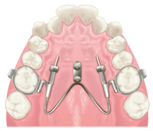
Figure1. SHU-form
The SHU-lider device is a mini-screw anchored maxillary molar distalizing device manufactured with the SHU-form design in the palate through the application of CAD/CAM technology. To date, a prefabricated plate or ring have been used most commonly as the abutment for connecting with the heads of the mini-screws. The SHU-lider device features a custom-made superstructure by utilizing CAD/CAM technology composed of a coupling, which is fixed with the head of the anchor screw, a connector, and a guide (Figure 2). The connector extends in a plate shape from the posterior coupling toward the distal palatal portion of the molar. At the plate end of the distal palatal portion of the connector, the guide for sliding the molars mesiodistally is connected so as to pass near the center of resistance of the maxillary molars from the distal to the mesial direction. This guide can be welded with a stainless-steel wire, it is also possible to manufacture a guide by applying CAD/CAM technology.
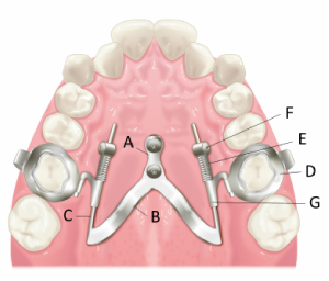
Figure 2. SHU-lider device. A: Coupling, B: Connector, C: Guide, D: Molar band, E: Open-coil spring, F: Activation lock, G: Sliding hook
It is necessary to use molar bands, open-coil springs, activation locks, and sliding hooks inserted into the palatal sheaths on the molar bands as a component for directly exerting orthodontic force on the maxillary molars. The distalizing force is delivered by opencoil springs, activated by activation locks, to sliding hooks inserted into lingual sheaths on the molar bands. The molar bands, palatal sheaths, and sliding hooks can also be custom-made by CAD/CAM technology.
The patient was a 10-year-old boy with insufficient space for canine eruption, and therefore distal movement of maxillary molars was performed. Two mini-screws were inserted in the hard palate (Figure 3). The impression of the heads of the mini-screws, palatal gingiva, and all teeth was taken with an intraoral scanner (Figure 4). Virtual planning of the SHU-lider device was performed by using a CAD software (Figure 5 and 6). Based on the digital design, the coupling, connector and molar bands were printed three dimensionally with metal alloy utilizing a laser-melting machine and manufactured in a custom-made manner. The SHU-lider device were placed on a three-dimensional printed model (Figure 7). The connector and the guide made of stainless-steel wire were welded together. The molar bands were bonded to the bilateral first molars and the coupling were fixed to the heads of the mini-screws. It can be fixed at a predetermined position in the oral cavity (Figure 8). After maxillary molar distal movement, it is possible to cut the anterior part of the guide short. Because there is no superstructure in the anterior center part of the palate, the tongue is less uncomfortable, and myofunctional therapy of the tongue can be performed.
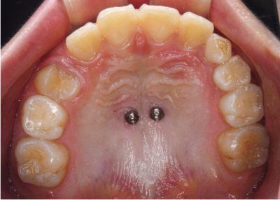
Figure 3. Two mini-screws positioned in the palate
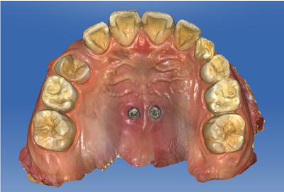
Figure 4. Image taken by intraoral scanner after placement of mini-screws
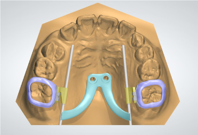
Figure 5. Virtual planning of the SHU-lider device
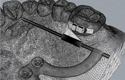
Figure 6. The custom-made coupling, connector and molar bands.
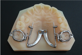
Figure 7. The SHU-lider device placed on three-dimensional printed model
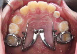
Figure 8. Intraoral fixed the SHU-lider device
By taking an impression with the intraoral scanner, it is possible to accurately reproduce the three-dimensional positional relationship between the heads of the mini-screws, palatal gingiva, and teeth, and to manufacture the orthodontic device. In particular, because it features superior adaptation of the heads of the mini-screws and the coupling, it appears that the unexpected overload to the mini-screws at the time of fixation can be prevented.
Because the SHU-lider device is mainly composed of a hard metal plate, compared with a conventional maxillary molar distal movement device using anchor screws in the palate with sliding mechanics, deflection of the superstructure, in particular, the connector and the guide, due to the reaction of the orthodontic force of the open coil spring tends not to occur. Hence, it is possible to ensure distal movement of the maxillary molars toward the position as intended, and it is also possible to prevent buccal inclination and mesial rotation during maxillary molar distal movement.
In the SHU-lider device, because the superstructure connected to the heads of the mini-screws is not located at the anterior portion of the palate, the tongue experiences a relatively low degree of discomfort and the device is less likely to cause stimulation or damage to the tongue. Therefore, it does not tend to be an obstacle to myofunctional therapy in patients with lingual dysfunction. In addition, the mesial end of the guide can be shortened after the distal movement of the maxillary molars, resulting in a more compact form. When performing retraction of the anterior teeth using molars as indirect anchorage after molar distal movement, the anchorage loss of the molars can be prevented by using a hard metal plate. Furthermore, even in cases in which retraction of the anterior teeth is greatly performed after maxillary molar distal movement, the stainless steel wire does not contact or dig into the anterior palatal mucosa.
The SHU-lider device is a novel mini-screw anchored maxillary molar distalizing device with the SHU-form design through the application of CAD/CAM technology. By taking an impression with the intraoral scanner and using a CAD/CAM technology, it is possible to accurately reproduce the three-dimensional position in the oral cavity and to manufacture this device with superior adaptation. Because the superstructure is mainly composed of a hard metal plate, it is possible to distally move the molar to a desired position with little deformation of the device when the orthodontic force is applied. In addition, when using the molar as an indirect anchorage after maxillary molar distal movement, more stable indirect anchorage can be established. Because the superstructure is not located in the anterior part of the palate, the tongue experiences relatively little discomfort, and it is less likely to interfere with myofunctional therapy for patients with lingual dysfunction.
- Antonarakis GS, Kiliaridis S (2008) Maxillary molar distalization with noncompliance intramaxillary appliances in Class II malocclusion. A systematic review. Angle Orthod 78: 1133-1140. [Crossref]
- Caprioglio A, Beretta M, Lanteri C (2011) Maxillary molar distalization: Pendulum and Fast-Back, comparison between two approaches for Class II malocclusion. Prog Orthod 12: 8-16. [Crossref]
- Choi YJ, Lee JS, Cha JY, Park YC (2011) Total distalization of the maxillary arch in a patient with skeletal Class II malocclusion. Am J Orthod Dentofacial Orthop 139: 823-833. [Crossref]
- Graber T (1955) Extraoral force - facts and fallacies. Am J Orthod 41: 490-505.
- Oosthuizen L, Dijkman JF, Evans WG (1973) A mechanical appraisal of the Kloehn extraoral assembly. Angle Orthod 43: 221-232. [Crossref]
- Toy E, Enacar A (2011) The effects of the pendulum distalising appliance and cervical headgear on the dentofacial structures. Aust Orthod J 27: 10-16. [Crossref]
- Costa A, Raffainl M, Melsen B (1998) Miniscrews as orthodontic anchorage: a preliminary report. Int J Adult Orthodon Orthognath Surg 13: 201-209. [Crossref]
- Kanomi R (1997) Mini-implant for orthodontic anchorage. J Clin Orthod 31: 763-767. [Crossref]
- McSherry PF, Bradley H (2000) Class II correction-reducing patient compliance: a review of the available techniques. J Orthod 27: 219-225. [Crossref]
- Wilmes B, Drescher D (2008) A miniscrew system with interchangeable abutments. J Clin Orthod 42: 574-580. [Crossref]
- Wilmes B, Drescher D, Nienkemper M (2009) A miniplate system for improved stability of skeletal anchorage. J Clin Orthod 43: 494-501. [Crossref]
- Wilmes B, Drescher D (2010) Application and effectiveness of the Beneslider: a device to move molars distally. World J Orthod 11: 331-340. [Crossref]
- Nienkemper M, Wilmes B, Pauls A, Yamaguchi S, Ludwig B, et al. (2014) Treatment efficiency of mini-implant-borne distalization depending on age and second-molar eruption. J Orofac Orthop 75: 118-132. [Crossref]
- Aragon ML, Pontes LF, Bichara LM, Flores-Mir C, Normando D (2016) Validity and reliability of intraoral scanners compared to conventional gypsum models measurements: a systematic review. Eur J Orthod 38: 429-434. [Crossref]
- Graf S, Vasudavan S, Wilmes B (2018) CAD-CAM design and 3-dimensional printing of mini-implant retained orthodontic appliances. Am J Orthod Dentofacial Orthop 154: 877-882. [Crossref]