Abstract
Safety is the main design factor for any designer who creates or develops a new object. Involving aluminium to design the car longitudinal members has many benefits such as decreasing weight, decreasing the environment pollution and reducing fuel consumption. Bi-Metallic longitudinal member is created with both steel and aluminium materials. Four types of trigger have been modified, circular, elliptical, triangular and beaded to reduce the peak load and enhance the energy absorption values. Moreover, the percentage and position for the trigger geometry is studied. Circular trigger with 5% reduction was chosen as the best trigger due to enhancing energy absorption and reducing the peak load values.
Key words
specific energy absorption, FEA, car safety, crashworthiness applications
Introduction
The two basic approaches are in automotive design and in material selection, and they are closely related. Regarding materials, there has been a trend toward the use of light metals and their alloys in automotive components, particularly automotive bodies [1,2]. The most commonly used materials are aluminium, magnesium, and their alloys; though some research has also been done on the use of titanium, zinc, and non-metallic materials [3]. On the other side however, there has been strong competition from the steel industry. Both sides face important design issues. As a result there are a host of new light alloys intended for automotive use, together with new designs especially adapted for these alloys and also a host of new steel-based designs that make more efficient use of steel than was formerly typical [4].
Reyes et al., studied the metallic cylindrical shells and found they are commonly used structural elements. Besides their high stiffness and strength combined with a low weight they offer a high specific energy absorption capacity when subjected to axial loading [5]. Aluminium material is special due to its characteristics, which are corrosion resistance, strength, recyclability, lightweight, durability, ductility and formability [6]. This unique combination of properties makes aluminium suitable for a variety of applications. The aluminium can be formed, cast and machined. Often equipment and fabrication methods used for steel can be used in aluminium. Aluminium is used extensively in space frame technological. This technology is projected to have the effect of conservation in fuel consumption of over 10%, weight saving of over 25%, and improvement in impact durability of 20% [7]. Furthermore, Langseth et al., found that the aluminium can be recycled with an energy input to 5% of the energy needed to produce primary aluminium [8]. An alloy is a mixture of two or more metals, made with the objective of improving the properties of one of these metals, or, in some cases, producing new properties not possessed by either of the metals in the pure state [9,10].
Triggering mechanism has significant effect on tubes which include corners in the geometry; the load-displacement curve does not vary greatly but the first beak load has decreased which is preferable to get smooth fluctuation curve level [11]. Langseth et al., and Santosa et al., used the imperfection method for the half wave cosine on the corner of the shape [12-15]. Lu et al., and Tot ten et al., [16,17] the triggering mechanism is sufficient with car application, trigger shapes implemented with a good strategy on the model length.
Car safety has priority for the designers, longitudinal members energy absorption capability has to be improved. Many studies for thin walled tubes have been carried out and subjected under dynamic and static load to examine the behaviour of these tubes and the energy that can be absorbed. The numerical study using abaqus software has done with many triggering mechanisms for the longitudinal member tube to get preferable folding patterns and improve the fluctuation of the force-displacement curve.
Model description
A rectangular profile with a 90 × 60 × 2 dimension has been simulated with different trigger geometries. The triggering method has taken out the material along the wall perimeter around two sides. This method has been used only for the steel tube for two reasons, firstly, to reduce the manufacturing cost or tube simulation number; secondly, the steel is affected primarily with the load applied by the impactor. The initiator distance of ½ × 45 = 22.5 is the distance from the first end close to the impactor. The rectangular profile with the new trigger initiators was simulated with the mass of 275 kg and 15 m/s velocity (Figure 1).
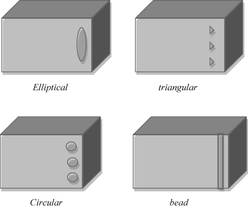
Figure 1. Schematic pictures of the four initiator geometries
The triggering area for the rectangular surface reduces the perimeter by 10 percent. The reduction for all triggering geometrical shapes is the same to get good comparison results. Triangle, circular, elliptical and bead initiators are the chosen geometrical shapes for the triggering method as shown in the Figure 1. Figure 2 shows the perimeter calculation for circular and bead initiators.
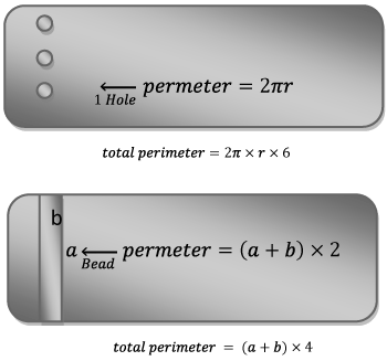
Figure 2. Perimeter calculation of the circular and bead initiators
Front Car model has been created by the finite element analysis program using ABAQUS/ CAE software. Shell element used for the longitudinal members design to develop them and improve the energy absorption capability. Thickness for each shape assigned for steel and aluminium together. Bi-Metallic material is a new method which has been involved through this project; each tube has 2 mm and 1 mm for steel and aluminium respectively. Dynamic load applied with 54 km/h to make the collision for the tubes like in real. Bi-Metallic material improved the long folding pattern procedure with high strength capability.
The lower rigid body welded with the tubes through tie constrain interaction type, while the upper impactor just connect with node to surface interaction type with the contact area of the bi-metallic tube. Surface to surface assigned between outer and inner tubes to be recognised like a separate parts, the two tubes welded from upper edges. Surface to surface contact type used to avoid any penetration could be happened between the two tubes (Steel and Aluminium)
All model parts have assigned and assembled together. In crash applications the model needs an impactor, this impactor is movable which has one axis motion (first degree of freedom). The velocity and mass have to be assigned through the impactor. While the bottom impactor assigned to be fixed (0 degree of freedom). Quadrateral mesh type with a 5 mm global mesh size has set for the tubes, small mesh size led to more number of nodes and produce more results accuracy. Bi-Metallic tube with two rigid bodies’ model clearly seen in Figure 3.
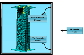
Figure 3. Rectangular tube model
Crashworthiness parameters
Energy absorption
When evaluating the crashworthiness performance of energy absorber devices, attention should be directed to the instantaneous crush behavior, such as, crush force efficiency (CFE), crushed strain (CS), failure modes in different stages of the crushing process and energy absorption capabilities. Composite materials have been found to absorb more energy compared with the conventional materials, such as, metal, on the basis of the specific energy [18,19] (Figure 4).
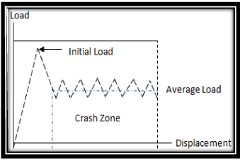
Figure 4. An ideal vs. A typical load-displacement diagram for energy absorbing devices
The purpose of the thin walled tube is to convert the kinetic energy due to collision to other that can be absorbed by the tube due to plastic deformation. Other purpose of the tube is to reduce the peak force associated during impact. High level force results high deceleration value that causes irrecoverable brain damage [11]. The total energy absorbed (EA) is the area under the load/displacement curve, which is a function of the specimen cross-sectional area and the material density, and can be obtained numerically by integrating the load displacement load curve [12].
Crush force efficiency
Crush Force Efficiency is the ratio between the average crushing load and the maximum crushing load. It is useful to measure the performance of an absorber [13]. If the ratio is close to unity, the absorber is crushing at a value close to the peak load, hence minimising the changes in deceleration, as desired from any absorber design. On the other hand, if this ratio is away from unity, there are rapid changes in the deceleration and this is dangerous to have in the design of a vehicle. In general, as the CFE value approaches unity, the better is the performance of the energy absorbing structure [13].
Effect of different initiator types on crashworthiness parameters
Different types of initiators have been designed for the rectangular bi-metallic tube (Bead, Circular, Elliptical and Triangular) to examine the crashworthiness parameters and crash behavior under dynamic load. Figure 5 illustrates the force levels for the four triggering profiles compared with the no-triggering profile. The reduction of the first peak load is clearly shown with the profiles and the initiators. The circular initiator produced the lowest value of peak load of 214 kN compared with the original profile without the initiator of 224 kN as shown in Figure 6.
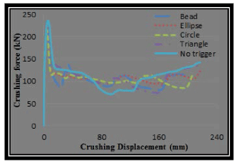
Figure 5. Load-displacement curves for the four initiator types with no initiator tube.
The stability of the behavior for the initiator profiles is due to the regular folding pattern. This stability occurs due to the regular fold happening for the profiles with initiators, which the results have required for this technique. Circular initiator produces a smooth fluctuating curve (Figure 5) compared to the original no initiator tube which exhibits bad behavior under dynamic load.
Figure 7 included the crash force efficiency (CFE) that is an important criterion in the crashing stability; the decreasing of the first peak load means an increasing in the crash force efficiency value. The circular initiator exhibited the highest value for the CFE with a slight difference with the ellipse initiator. The CFE has improved for circular tube compared to the original tube. Bead and triangle initiators were very bad and not preferable shapes.
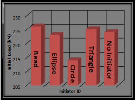
Figure 6. Initial peak load values of the four initiator types and no initiator tube
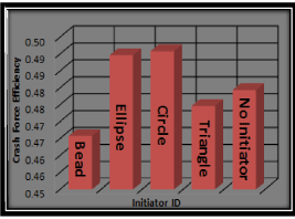
Figure 7. Crash force efficiency values of the four initiator types and no initiator tube
Energy absorption values of the initiator and no initiator profiles illustrated in Figure 8. Energy absorption of the initiators or the original profiles with less reduction of the force level has higher energy values due to the higher average force levels. The initiator importance is in weakening the structure in a suitable position so that it causes the decreasing of the energy absorption. Stability and regularity for the force level along the crushing displacement and folding pattern are more important than the energy absorption. The energy absorption value can be increased by increasing the thickness by a small value. All parameter values can be clearly seen in Table 1.
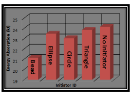
Figure 8. Energy absorption values of the four initiator types and no initiator tube
Table 1. Different initiator types crashworthiness parameters values
|
Parameters
Trigger
Type
|
Energy absorption
(kj)
|
Peak load
(kn)
|
Crash force efficiency
|
|
Without trigger
|
24429
|
226
|
0.466
|
|
Bead trigger
|
21280
|
222
|
0.489
|
|
Ellipse trigger
|
23753
|
214
|
0.491
|
|
Circular trigger
|
23269
|
225
|
0.475
|
|
Triangle trigger
|
24073
|
224
|
0.479
|
The visualizations of the deformed profiles are important to make the choice for the most suitable initiator. The force level does not clearly present where the folds happened and how the regularity is seen. Figure 9 shows the deformed profiles of four initiators. From the four full crash initiator profiles, it is clear that the circular initiator is the most regularly deformed profile; the bead is the worst initiator deformed and the increased peak load due to the rotation of the cross-section is caused by the weakening for the closeness to the corners of the rectangular profile structure. The elliptical initiator produced a good folded pattern but is still less than the circular initiator because of the small covered initiation area of the two structure sides.
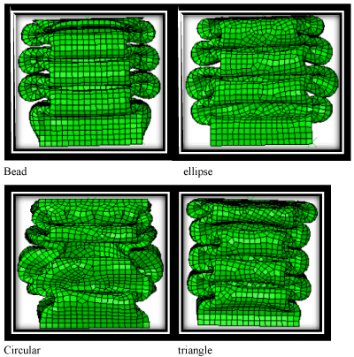
Figure 9. Deformation of the rectangular profile with different initiators
The lowest peak force level, regularity of the force-displacement curve and folding pattern stability are the three important parameters to make the decision of the best initiator; the circular initiator is the preferable initiator based on the three parameters above.
Determination of the best circular initiator area
Weakening of the cross-section has been applied by the triggering technique with four initiator geometries and the circular initiator was the most suitable for this technique; the reduction of the peak load was little and the folding pattern needs to be improved. The rectangular profile with a perimeter of 300 mm has been simulated with different initiator perimeter’s reduction (5%, 10% and 15%).
Figure 10 shows three different perimeter reductions of 5 per cent, 10 per cent and 15 per cent compared with the original profile without an initiator. The lowest peak load level was observed by the profile with a 15 per cent reduction perimeter, the same profile exhibited a regular fluctuation curve, which means it has the proper-folding pattern along the total crushing length. The increasing of the perimeter reduction causes a reduction of the peak load level. A regular folding failure mode gave the force level more stability which also affects the values of the energy absorption as seen in Figure 11. As explained before (section 3.1), energy absorption value can be obtained by multiplying the force by the crashing distance. C2 exhibits more energy than C3 tube. The more force level the more energy value.
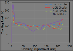
Figure 10. Force-deformation curves of rectangular profile with different trigger initiator areas
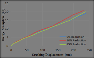
Figure 11. Energy curves of rectangular profile with different trigger initiator areas
The behaviour of the rectangular profile with different initiator reduction perimeters, 5, 10 percent and 15 percent reduction illustrated briefly in Figure 12,13 and 14 respectively. 10 percent and 15 percent perimeters produce more stable folding patterns than 5 percent circular. It is clearly shown that the beginning of failure patterns for C2 and C3 were from the top of the tubes, which is preferable to avoid any damage for any part of the car. The stress area for C1 was high on the bottom of the tube, and the folding patterns starting there as shown in Figure 12. The stress of the crashed tubes for circle trigger C1 and C2 were concentrated on the top of the tubes then distributed to the whole tube length to produce regular folding pattern failure mode.
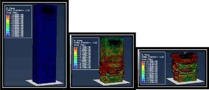
Figure 12. Deformation of the rectangular profile with 5% reduction percentages (c1)
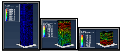
Figure 13. Deformation of the rectangular profile with 10% reduction percentages (c2)
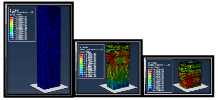
Figure 14. Deformation of the rectangular profile with 15% reduction percentages (c3)
More initial load also gave the advantage for C2 to increase the ability to absorb more energy during the crash, the values of initial failure load can be seen in Figure 15. From this figure it can be concluded that the trigger mechanism always reduces the value of initial failure load. Increasing the hole reduction percentage also decreases the initial peak load.
Increasing the ability of the tube to produce good folding failure mode due to increasing the hole reduction percentage lead to improving the average force. Increasing the average force value gave the tube C3 the chance to increase the crash force efficiency (Figure 16 and Table 2).
Table 2. Different initiator reduction crashworthiness parameters values
|
parameters
Trigger
Type
|
Energy absorption
(kj)
|
Peak load
(kn)
|
Crash force efficiency
|
|
Without trigger
|
24.429
|
226
|
0.466
|
|
5% reduction
|
23.562
|
219
|
0.494
|
|
10% reduction
|
23269
|
214
|
0.505
|
|
15% reduction
|
22282
|
207
|
0.480
|
Conclusion
Trigger of the tube means apply specific weaknesses in a proper position. The purpose of trigger is to get a stable force and regular folding along the deformation tube length. Four types of initiators have been studied, bead, triangle, circle and elliptic. The lowest peak force level, regularity of the force-displacement curve and folding pattern stability are the three important parameters to make the decision of the best initiator; the circular initiator is the preferable initiator based on the three parameters above. It was necessary to increase the circle hole diameter in order to examine the tube with more weakening. While weaknesses much as desired in spite of giving regular folding process but show decreases in energy absorption and stiffness and hence decreases in bending resistance. The 15 per cent circular initiator C3 produced the lowest energy absorption and lowest peak load; at the same time, it increased the stability of the crushing behaviour and decreased the peak load level. These are more important than the energy absorption; therefore, the 15 per cent circular initiator is the preferred initiator for this study.
Acknowledgements
The authors would like to thank to Curtin University, Sarawak for the financial and technical support in this research program. Ibra College of Technology is gratefully acknowledged.
References
- Marsolek J, Reimerdes HG (2004) Energy absorption of metallic cylindrical shells with induced nonaxisymmetric folding patterns. Int J Impact Eng 30: 8-9.
- Pled F, Yan W, Wen C (2007) Crushing Modes of Aluminium Tubes under Axial Compression. 5th Australasian Congress on Applied Mechanics. ACAM 10-12.
- Zaini Ahmed (2009) Impact and Energy Absorption of Empty and Foam-filled Conical Tubes, Queensland University of Technology Australia.
- Mahmood HF, Paluszny A (1981) Design of thin wall columns for crash energy management - their strength and mode of collapse. SAE Technical Paper 811302.
- Reyes A, Hopperstad OS, Langseth M (2004) Aluminium foam-filled extrusions subjected to oblique loading: experimental and numerical study. Int J Solids Structure 41: 1645–75.
- Tot ten GE, MacKenzie DS (2003) Handbook of Aluminium, 1stedn. New York: Marcel Dekker.
- Kim D-K, Lee S (1999) Impact Energy Absorption of 6061 Aluminium Extruded Tubes with Different Cross-Sectional Shapes. Materials and Design. 20: 41-49.
- Langseth M, Hopperstad OS, Hanssen AG (1998) Crash Behavior of Thin-Walled Aluminum Members. Thin-Walled Structures 32: 127-150.
- Jackson KE, Fasanella EL (2003) Test-Analysis Correlation of a Crash Simulation of a Vertical Drop Test of a Commuter-Class Aircraft, U.S. Army Research Laboratory, Vehicle Technology Directorate NASA Langley Research Center Hampton, VA.
- Higgins RA (2006) Materials for Engineers and Technicians. 4thedn. UK: R. A. Higgins and W. Bolton
- Babbage J, Mallick PK (2002) Crash Resistance of Aluminum Composite Hybrid Tubes, Proceeding of 17th Annual Technical Conference of the American Society for Composite, Paper No. 070.
- Langseth M, Hopperstad S, Hanssen AG (1998) Crash Behavior of Thin-Walled Aluminum Members. Thin-Walled Structures 32: 127-150.
- Santosa SP, Wierzbiki T, Hanssen AG, Langseth M (2000) Experimental and Numerical Studies of Foam-Filled Sections. Int J Impact Eng 24: 509-534.
- Marshall NS, Nurick GN (1998) The Effect of Induced Deformations on the Formation of the First Lobe of Symmetric ProgressiveBuckling of Thin Walled Square Tubes. Structures Under Shock and Impact _SUSI 98_ Thessaloniki, Greece, Jun. 24–26, N. Jones, D. G. Talaslidis, C. A. Brebbia, and G. D. Manolis, eds.,: 155–168.
- AL-Qrimli HF, Khalid KS, Mahdi FA (2015) The effect of cone angle on composite tubes subjected to axial loading, British Journal of Applied Science & Technology. Sci Domain Int 7: BJAST.2015.152.
- Lu G, Yu T (2003) Energy absorption of structures and materials, 1stedn. New York: Woodhead Publishing Limited.
- Tot ten GE, MacKenzie DS (2003) Handbook of Aluminum,1st edn. New York: Marcel Dekker.
- AL-Qrimli HF, Oshkour AA, FB, Mahdi FA (2015) Material Design Consideration for Gear Component Using Functional Graded Materials. Intl J Materials Eng Innov : 61/5/2016
- Fernández MV, de Moura MFSF, da Silva LFM, Marques AT (2013) Characterization of composite bonded joints under pure mode II fatigue loading. Composite Structures 95: 222-226.


